Serial-I2C adapter
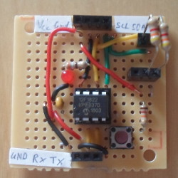
06 May 2018About half a year ago I wrote the firmware for a basic I2C-RS232 bridge, although it was really an exercise in learning I2C and RS232 programming, with much of the actual effort spent going in circles due to what turned out to be bugs in gpsim. It was never implemented in hardware because at the time I was still building the LED matrix display, which would later gain an RS232 interface. This circuit is a wiring up of a
PIC12F1822 which has been programmed to act as a basic RS232-controlled I2C master.
The motive for the circuit was due to the USB-ISS USB I2C master not playing ball with a new expander chip I was tying out, which I suspected might be due to the built-in 4.7kΩ pull-up resistors being too strong for an interface that was supposedly electrically compatible with SMBus. Before long I realised I had all the components and prerequisite knowledge to build my own adapter, and in any case it would give more opportunity to debug what was going wrong with the transactions.
Circuit design parameters
The original idea was to use thePIC16F1823, which is basically the PIC12F1822 with six extra I/O pins, so that multiple LEDs could be used. Although superficially a drop-in replacement for the USB-ISS, a primary design goal was much better transaction debugging. On such a small circuit, there are only a few design decisions:-
- I2C receptacle wiring
- The first test of this board was to be driving the LCD display PCB, so the pinning of 4-slot receptacle was chosen to allow the latter to be plugged straight in.
- Pull-up resisitor receptacles
- Inappropriate pull-up resistors on the I2C control lines was a working assumption when this circuit project was started, and for convenience I decided to include receptacles for them in the circuit board rather than expect them to be wired externally. A three-hole receptacle was used in order to provide a second Vcc connection.
- Status LED
- The original ideas was to use multiple LEDs to expose information on failed I2C transactions, but in the end it was decided this information could be relayed via RS232 return codes. It blinks if an I2C transaction was successful, and stays lit if it failed.
- Reset button
- A reset button was added because the pin could only be used for input, although in practice recovery routines within the firmware proved robust enough to not require it. The pull-up resistor is technically unnecessary, as the
PIC12F1822has internal pull-ups, but I added it through force of habit.
Firmware
The firmware for the I2C master is a mini-project within my Bitbucket repository, and implementation-related comments are within the source code itself at that location rather than here. Apart from a change from interrupts to polling the top-level structure is much the same as the I2C-RS232 firmware, and below are some general design remarks that are specific to this I2C master firmware.Serial protocol
Although clearly inspired by the command protocol used by theUSB-ISS, it is deliberately different — this is partly to avoid being seen as a simple copy, partly to simplify implementation, and partly to make thing a bit more intuitive. The main difference is that mode is simply the number of register address bytes, and at least for writes how the mode & register bytes are handled is the same as how the count & data bytes are handled. The command layout is shown below:
| Slave addr | Mode | Register | Register | Count | Data |
| LSB is read bit | 0, 1, or 2 | Modes 1 & 2 | Mode 2 only | 0-32 | Writes only |
The return value sent back to the host via RS232 always includes at least two bytes: The first is a success/failure indicator, and the second gives further information. On success the first byte is 0x01 and the second byte gives the number of bytes read/written; for a successful read subsequent bytes are the read data. On failure the first is 0x00 and the second byte is the index of the command byte that the error notionally occurred on — the table below gives an interpretation:
| Error code | Mode | 0 | 1 | 2 |
| 1 | Invalid mode | ||
| 0 | No slave address Ack | ||
| 2 | Overrun | Reg Nack | |
| 3 | Data Nack | Overrun | Reg Nack |
| 4 | Data Nack | Overrun | |
| 5+ | Data Nack | ||
An overrun is when the count is larger than the internal buffer, and an I2C transaction does not take place.
BAUD rates
RS232 BAUD rates, which I have covered in the past, seems to be one of those things that I don't get quite right whenever I mention it. This in part may well be down buggy simulators when I was trying to first work the stuff out, the main wrong misconception being about what BAUD rates are actually supported by various PIC micro-controllers. ThePIC12F1822 actually includes a lot of different factors, such as different clock pre-scaling and whether the BAUD rate generator timer is 8-bit or 16-bit — with BRGH=1 (High BAUD rate) and BRG16=1 (16-bit generator) FOsc is divided by 4 rather than 16 or 64, so in theory a BAUD of 1,300,000 could be supported. For this circuit rs232Setup() targets 57,600 as the RS232 line speed.
One factor that plays a part with BAUD rate is that it is not exact — the actual BAUD rate is 16M/4*(68+1)=57971, which is out by 371 (i.e 0.64%). With RS232 there is some tolerance for error, as explained in an external article — as long as the two UARTs engaged in communication don't go out of sync between the start and stop bit, any error is not an issue. The complicating factor is that an inexact BAUD rate adds to any jitter, and in many cases accuratcy of the remote UART that the micro-controller communicates with is unknown. My interpretation of a Stackoverflow article is that BAUD inaccuracy should be kept under 1%.
Remarks
The original purpose of this project was to see whether a certain I2C-driven chip would be any use to me at all, a test that came back positive, and in the process I improved my I2C code firmware code. While not perfect, I felt that the mini-project went as smoothly as can reasonably be expected, and for what sums to a day or two of effort I feel the results are good.Influence of the perfboard
If I did not have the small prototyping perfboards (Farnell 2768276), I have doubts whether this mini-project would have been started, and it certainly would not have been competed. I was initially thinking of wiring up aPIC12F1822 with some make-shift firmware just to see whether the expander would work with what is my usual I2C-enabled microcontroller, but having the small prototyping boards in stock keeps me on the lookout for interesting mini-projects, and this gave the final push towards the idea of making my own complete I2C master firmware.
GPsim
I have always had mixed feelings about gpsim, but since I already had a test circuit laid out from the I2C-RS232 bridge project, it overall was a great help in both getting the RS232 protocol together and initial checking of the extended I2C routines. In recent projects I have mostly avoided it because it is not able to provide a useful abstraction of the physical circuit the firmware is being built for, and had I not already had an RS232/I2C test circuit I doubt I would have used it this time round.Firmware as ongoing project
At time of publication the firmware was functional, but the testing of read functionality was minimal compared to write functionality, and the firmware code itself was not “complete” because I felt at the very least it needed a significant amount of clean-up. This is the first circuit for which the firmware from the start was a parallel open-source mini-project , and I feel that such a split has worked well because trying to perfect the firmware does not hold up what is in essence a complete write-up.USB interface
Although I did have both USB connectors and USB-RS232 interface chips in stock, I did not have any suitable break-out boards, so I stuck with assuming TTL-level RS232 input via aTTL-232R-3v3. I am undecided whether trying out the USB-RS232 chip will be an extension of this I2C master, possibly involving PCB design, or an independent mini-project.