RS232 wire-line
01 November 2017RS232 voltage levels is something I have touched on in the past but so far have not really addressesed in depth. Although the USART modules in various PIC microcontrollers implement the RS232 protocol, this does not extend to the electrical characteristics expected by RS232 interfaces, and as a result they cannot be directly attached to a PC serial port without blowing the whole IC. RS232 typically uses ±13 volts to represent the high and low parts of a bit-stream, but it can be as high as ±25 volts. These voltage levels are used to avoid problems with electrical interference, as RS232 is intended for external interfaces, but these voltages are vastly above the 3-5 volts used by most integrated circuits. This article will cover the practicalities of using RS232 to communicate off-circuit.
TTL-level USB adapters
For debugging purposes there are USB RS232 adapters that use TTL voltage levels rather than RS232 ones, and the two I have are the FDTITTL-232R-3V3 (Farnell 1329311) and TTL-232R-5V (Farnell 2419945). They use 3.3 volt and 5 volt TTL levels respectively, although both are 5 volt tolerant and I have had no problems using the TTL-232R-3V3 in 5 volt circuits. The wiring for both is as follows:
| Wire Colour | function | |
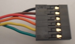 |
Black | Ground |
| Brown | CTS | |
| Red | Vcc | |
| Orange | Tx | |
| Yellow | Rx | |
| Green | RTS |
In practice the Ground, Transmit, & Receive pins are the only ones most people will be interested in. The Vcc is circa 5 volts from the USB port, but given past experience with relying on USB power, I would avoid using it for powering anything other than an individual chip.
RS232 drivers
In order to attach normal RS232 interfaces to a microcontroller, an RS232 driver is required, which converts between RS232 standard and TTL voltage levels. For demonstration purposes I will use theADM232AANZ (Farnell 1438715), which uses external capacitors in order to obtain the voltage levels required for RS232. In the circuit below it converts between a TTL-232R-3V3 TTL-USB adapter and a generic RS232-level USB adapter (Burn Technology BT232G) of which I have forgotten the supplier of.
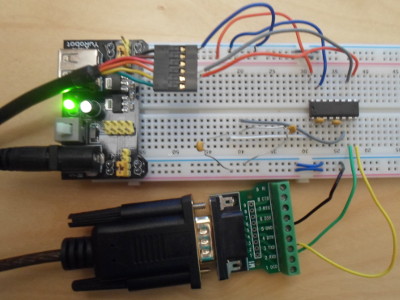
I omitted a capacitor between Vcc and ground as I assumed it was specified for current-smoothing tasks already dealt with by the power supply circuitry. From the RS232 adapter the green wire is from receive and the yellow wire from transmit; on the other side orange is connected to receive and grey to transmit. It is hard to see in the picture, but the four capacitors I used are attached as follows:
- Pin 1 to Pin 3
- Pin 2 to Vcc
- Pin 4 to Pin 5
- Pin 6 to Ground