PIC12F1822 I2C-RS232 bridge
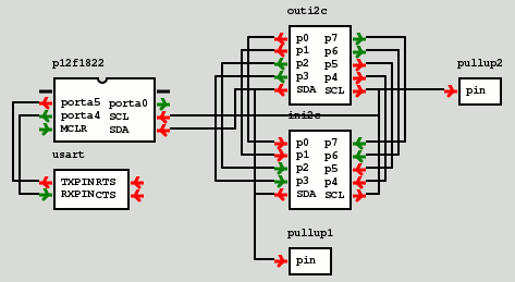
15 October 2017In this article the firmware for an I2C-RS232 bridge will be demonstrated, the purpose being to show the programming of both I2C and RS232 access. Two i2c2par (I2C to Parallel — in other words I/O Expanders) modules wired together will be used to demonstrate I2C reads and writes, and user control will be via an USART (RS232) module. For development purposes gpsim will be used, and the (virtual) circuit is shown below. This setup is somewhat contrived, as one would really use a single EEPROM rather than I/O Expanders wired together, but the setup used here makes it relatively easy to see what is happening.
The PIC12F1822 chipset will be used because it is one of the few chipsets I found that has both I2C & RS232 capability, and is supported by gpsim. In a later project this chipset will be used as the control for an I2C-based physical circuit, wheress this article focuses on the hurdle of figuring out serial programming in firmware.
gpsim issues
Overall I think gpsim is a great piece of software for getting started with PIC chip programming, but it clearly has/had issues with its USART and I2C modules. Of the four times I have had difficulty working out why my firmware code was not working, three of them were pretty much down to bugs in gpsim itself rather than my firmware. Wondering why my code wasn't working within gpsim I tried the firmware on a physical microcontroller, and it worked as expected. The code and this article was actually written a month ago, but it was only this weekend that all the bug reports I submitted were fixed.Programming issues
Having now used a few different PIC chip models, I now see why those who look for embedded programmers are very prescriptive about wanting experience with specific chipset models — a large portion of embedded programming is dealing with hardware interfaces rather than what could be considered software engineering. Conversely the implementation-specific mind-set also explains why some former embedded programmers are quite bad at writing code for desktop-based applications, namely the lack of awareness that doing stuff in a non-compliant way might not work further down the line. Below I highlight some of the issues that came up during this mini-project.Chipset clock speed
The main chip clock speed (FOSC) is set using OSCCON (page 65) and problems seem to arise if the instructions that follow it have anything dependent on clock timings. I have read various things related to clock start-up and stabalisation involving the OSCSTAT register but trying to act on them did not seem to make any difference. Most reliable thing seems to be to set chip clock speed as very first thing the firmware does and then do some other setup such as pin settings. Lot of the options are related to the use of an external timer. For me the only real option is to choose the internal oscillator running at 16MHz, as energy-efficency is not really a concern of mine, and both I2C and RS232 look like they will have problems with anything lower. I suspect the only reason the chip supports all these lower clock speeds that cannot sustain serial communications is because it is a common chip core that is used in multiple chip models. In cases where communications are not required, I would go for a cheaper part that has more pins.
Pin asignments
Because thePIC12F1822 chipset only has 6 functional pins, there is some flexibility in which pins are used for what. The I2C pins are fixed due to voltage issues, so to allow both I2C and RS232 at the same time I reassign the RS232 peripheral to pins on the other side of the chip. Analog functions also need to be disabled, and it is a mystery to me why they are on by default. The major down-side of this is that this chip needs a lot of setting up, which causes all sorts of complications while trying to work out how to do things.
These days I normally avoid using the MCLR as I have a slight suspicion that disabling it as a reset line can cause problems with reprogramming chips with external power, and the programming process means it can be subjected to voltages much higher than usual TTL levels. In any case it can only be used as an input, and in practice it is output pins that are needed for most things I have done so far. Given the choice I would also leave the pins required for programming unused as well, as it is easier than including isolation curcuitry required for in-circuit programming.
RS232 BAUD rate
Like I2C the RS232 BAUD is based on division of the core clock rate, and the data-sheet gives a worked example (page 280) for 9600 BAUD at a chip clock speed of 16MHz, which is nice as most serial devices default to this BAUD rate. I wouldn't want to use anything lower than this, and I doubt whether the chip can realistically sustain anything much higher. Given the resolution available for for clock division it looks like it was designed to handle very low BAUD rates with minimal jitter, whereas my use-case is the opposite: I want high BAUD rates and an not concerned about jitter as long as it works.RS232 voltage levels
Although the chip supports the RS232 protocol, connecting it directly to a PC RS232 port will blow the chip due to the voltage levels. For debugging purposes I have an RS232 USB adapter (Farnell 1329311) that uses TTL voltage levels rather than the RS232 voltages (typically ±13 volts but can be upto ±25 volts). In order to attach normal RS232 adapters an RS232 driver (eg. Farnell 1438715) is required, which converts between RS232 standard and TTL voltage levels. However building physical circuits was beyond the scope of this article.I2C clock rate
In I2C transmission clock rate is determined by the master, which somewhat counter-intuitively is specified by theSSP1ADD register — I'm guessing this is because this register is unused in master mode. The value is number of cycles of a clock that runs at a quarter of the speed of the main chip clock, and data-sheet Table 25-4 on page 262 gives a table of values for clock speed of 4MHz and above. I don't think lower clock speeds can sustain I2C within specified error margins.
Gotcha with I2C addresses
One thing that has caught me out is inconsistency when quoting I2C address values. Within the I2C protocol the octet that contains the address also contains the read/write flag as the least significant bit, and quite often (e.g. within the Microchip PIC data-sheets) this whole byte is considered to be the address. However other sources such as the FDTI data-sheets quote the value of the 7 address bits rather than the whole octet, hence my previous confusion of0x22 vs. 0x44 with the UMFT201 I2C adapter.
Interface design
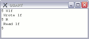
The interface is a simple command-line via the USART console which takes a single-letter command, eitherR for read or W for write. In the latter case a two-digit hexadecimal number is also required, and this is the value that is written to I2C. This interface is rather simple-minded and is not able to handle things like backspace and white-space, but robustness was not a goal here. In practice an RS232 command channel would be driven by a program, so sophisticated error handling is not really required.
The source files
I have only tried compiling these using SDCC and not Microchip's MPLABX C compiler, and I know that there are subtle syntax differences in the C code the two compilers support. Running this code also requires gpsim Subversion revision 2428 or later, as earlier versions have various bugs that prevent this code from working.Makefile
SRC=serial.c CC=sdcc FAM=pic14 CPU=12f1822 RM=rm GPSIM=/usr/local/gpsim-svn/gpsim $(SRC:.c=.hex): $(SRC) sdcc --use-non-free -m$(FAM) -p$(CPU) $^ clean: $(RM) $(SRC:.c=.asm) $(RM) $(SRC:.c=.hex) $(RM) $(SRC:.c=.cod) $(RM) $(SRC:.c=.lst) $(RM) $(SRC:.c=.o) clear:: $(RM) *~ run:: $(GPSIM) project.stc
project.stc
load serial.cod load board.stc
board.stc
module library libgpsim_extras module library libgpsim_modules p12f1822.BreakOnReset = true p12f1822.SafeMode = true p12f1822.UnknownMode = true p12f1822.WarnMode = true p12f1822.tmr1_freq = 32768 p12f1822.xpos = 144 p12f1822.ypos = 132 module load i2c2par ini2c ini2c.Slave_Address = 31 ini2c.xpos = 360 ini2c.ypos = 180 module load i2c2par outi2c outi2c.Slave_Address = 39 outi2c.xpos = 360 outi2c.ypos = 84 module load usart usart usart.rxbaud = 9600 usart.txbaud = 9600 usart.xpos = 144 usart.ypos = 216 module load pullup pullup1 pullup1.capacitance = 0 pullup1.resistance = 10000 pullup1.voltage = 5 pullup1.xpos = 360 pullup1.ypos = 288 module load pullup pullup2 pullup2.capacitance = 0 pullup2.resistance = 10000 pullup2.voltage = 5 pullup2.xpos = 516 pullup2.ypos = 132 node TX node RX attach TX p12f1822.porta4 usart.RXPIN attach RX p12f1822.porta5 usart.TXPIN node sda node scl attach sda ini2c.SDA p12f1822.porta2 pullup1.pin outi2c.SDA attach scl ini2c.SCL p12f1822.porta1 pullup2.pin outi2c.SCL node wire0 node wire1 node wire2 node wire3 node wire4 node wire5 node wire6 node wire7 attach wire0 ini2c.p0 outi2c.p0 attach wire1 ini2c.p1 outi2c.p1 attach wire2 ini2c.p2 outi2c.p2 attach wire3 ini2c.p3 outi2c.p3 attach wire4 ini2c.p4 outi2c.p4 attach wire5 ini2c.p5 outi2c.p5 attach wire6 ini2c.p6 outi2c.p6 attach wire7 ini2c.p7 outi2c.p7
serial.c
#include "pic12f1822.h" __code short __at (_CONFIG1) cfg0 = _FOSC_INTOSC & _WDTE_OFF & _MCLRE_ON & _PWRTE_OFF & _CP_OFF & _CPD_OFF; void rs232WriteByte(const char bite) { TXREG = bite; while(! (PIR1 & 0b00010000)); } void rs232WriteBytes(char bites[], int len) { int idxBite; for(idxBite=0; idxBite<len; idxBite++) rs232WriteByte(bites[idxBite]); } void rs232WriteHex(const int hex) { int hi = hex >> 4; int lo = hex & 0x0f; if( hi ) { if( hi < 10 ) rs232WriteByte( hi + '0' ); else rs232WriteByte( hi + 'a' - 10); } if( lo < 10 ) rs232WriteByte( lo + '0'); else rs232WriteByte( lo + 'a' - 10); } int hexToValue(int iHex) { if( iHex >= 'a' && iHex <= 'f' ) return iHex - 'a' + 10; if( iHex >= 'A' && iHex <= 'F' ) return iHex - 'A' + 10; if( iHex >= '0' && iHex <= '9' ) return iHex - '0'; return 0xff; } void i2cWaitIdle(void) { while( (SSP1CON2 & 0b00011111) || (SSP1STAT & 0b100) ); } void i2cWaitPending(void) { /* Reading SSP1IF immediately after writing SSP1BUF may * give incorrect value. Need to wait a cycle or two.. */ __asm nop nop __endasm; while( ! SSP1IF ); } void i2cStart(void) { SSP1IF=0; SEN=1; } void i2cSend(const int bite) { SSP1IF=0; ACKSTAT=0; SSP1BUF = bite; } void i2cStop(void) { SSP1IF=0; PEN=1; } void main(void) { /* 16Mhz clock freq */ OSCCON = 0b01111010; /* Input/output pins */ TRISA = 0b00101110; ANSELA = 0; /* RS232 setup */ BAUDCON = 0b00000000; SPBRGH=0; SPBRGL=25; APFCON |= 0b10000100; TXSTA &= ~0b00010000; TXSTA |= 0b00100000; RCSTA |= 0b10010000; /* I2C setup */ SSP1ADD = 0x27; SSP1CON1 = 0b00101000; SSP1CON2 = 0; SSPEN=1; /* RS232 handled via interrupts */ GIE=1; PEIE=1; RCIF=0; RCIE=1; /* Busy loop */ rs232WriteBytes("$ ", 2); while(1); } unsigned int valBuffer[4]; unsigned int cntBuffer = 0; void intr(void) __interrupt { int iValue; int iValue2; if( RCIF ) { iValue = RCREG; RCIF=0; if( iValue == '\n' || iValue == '\r') { if( cntBuffer == 0 ) return; if( valBuffer[0] == 'R' ) { i2cWaitIdle(); i2cStart(); i2cWaitIdle(); //while( (SSPCON2 & 0x1f)); i2cSend( (31 << 1) | 1 ); i2cWaitPending(); i2cWaitIdle(); if( ACKSTAT ) { PORTA |= 0b1; while(1); } SSP1IF = 0; i2cWaitIdle(); RCEN=1; i2cWaitPending(); iValue = SSPBUF; ACKDT=1; ACKEN=1; i2cWaitIdle(); i2cStop(); i2cWaitPending(); rs232WriteBytes("\n Read ", 7); rs232WriteHex( iValue ); rs232WriteBytes("\n$ ", 3); } else if( valBuffer[0] == 'W' && cntBuffer == 3) { iValue = hexToValue(valBuffer[1]); iValue2 = hexToValue(valBuffer[2]); if ( iValue == 0xff || iValue2 == 0xff ) { rs232WriteBytes("\n Error\n$", 9); cntBuffer = 0; return; } iValue = iValue << 4; iValue |= iValue2; rs232WriteBytes("\n Wrote ", 8); rs232WriteHex( iValue); rs232WriteBytes("\n$ ",3); cntBuffer=0; i2cWaitIdle(); i2cStart(); i2cWaitPending(); i2cSend(39 << 1); i2cWaitPending(); i2cSend(iValue); i2cWaitPending(); i2cStop(); i2cWaitPending(); } else rs232WriteBytes("\n Error\n$", 9); cntBuffer = 0; return; } if( cntBuffer < 4 ) { valBuffer[cntBuffer++] = iValue; rs232WriteByte(iValue); } } }