Timer-based LED control
30 October 2017This is a follow-on from my USB-controlled LED matrix display, where the Python-controlled I2C-USB adapter is replaced with a
PIC12F1840 microcontroller, which in turn receives commands that update the image being displayed on the LED modules. In the previous setup the effective I2C transaction time was impractically high for the latency requirements of refreshing an LED display, to the point that it was only good for a display of around 15 dots wide — here that limit is extended to 45 dots.
The original plan was to do away with the row driver board and have a microcontroller handle the rows directly, but a code refactor meant that the gains in doing away with I2C transactions for the row control became a moot point, and in any case I did not have a fourth column driver board to use the freed up I2C addresses. As a result this article is purely a firmware exercise with all the hardware except the microcontroller being practically identical to the previous USB-driven LED display.
Firmware development setup
Within gpsim, the development circuit is not that different from that used for my I2C to RS232 bridge, and is shown in the schematic below. Rather than having one I2C-to-parallel module acting as input to another, seven are acting as independent outputs, mirroring the I/O Expanders driving the LED modules in the previous project. The USART (RS232) is intended to receive updates to what the LED matrices display. Because of the way gpsim lays out traces completely automatically, getting a good layout involves moving components around until the tracking algorithm results in something that looks intuitive, so this schematic is not quite as good as I would like it to me.
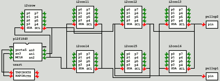
I did manage to create an LED matrix using LEDs & and gates, and although it is a bit of a strain for the gpsim GUI to handle, it nevertheless allows much of the firmware development to be done entirely using simulation. There are output polarity issues that need to be taken account of when the firmware is flashed to hardware, but otherwise the I2C-to-parallel modules are functionally identical to the PCF8574 I/O expanders that the LED display circuitry uses.
Timer module
The timer2 module is by the standards of other PIC modules actually quite simple — it basically generates an interrupt when a certain number of instruction cycles have passed. With the system clock (FOSC) set to 16MHz and both the pre-scaler & post-scaler set to their respective maximum values, thePR2 register corresponds to about a quarter-millisecond. In the firmware below, RA0 (LSB of PORTA) toggles every second:
#include "pic12f1822.h" __code short __at (_CONFIG1) cfg0 = _FOSC_INTOSC & _WDTE_OFF & _MCLRE_ON & _PWRTE_OFF & _CP_OFF & _CPD_OFF;
void waitMillis(unsigned char ms)
{
TMR2IF = 0;
PR2 = 4 * ms;
T2CON = 0b01111111;
while( ! TMR2IF );
}
void main(void)
{
unsigned short cntLoops;
OSCCON = 0b01111010;
TRISA = 0b00111110;
ANSELA = 0;
while(1)
{
cntLoops = 0;
while( cntLoops < 100 )
{
waitMillis(10);
cntLoops++;
}
PORTA ^= 0b1;
}
}
Nice thing about this compared to a busy-loop is that other interrupts are not disruptive to the timing, and in the unlucky case of the timer value being reached during an interrupt, the extra delay is only the amount of time before the interrupt finishes since the TMR2IF flag is latched.
Row refresh
Updating each of the six column driver boards is done as a single multiple-write transaction using I2C restart rather than as seperate independent transactions as done previously. An outline of this is shown by the firmware snippet below. Although the notional overheads of the function calls are relatively large, optimising them out won't make much difference as it is the waiting for the I2C bus that takes up instruction cycles. In order to avoid vertical smearing during refresh, the first transaction turns off all rows, and the last turns on the row being refreshed.
void updateRow(char idxRow)
{
i2cWaitIdle();
i2cStart();
i2cWaitPending();
i2cSend(0x40);
i2cWaitPending();
i2cSend( 0xff );
i2cWaitPending();
i2cRestart();
i2cWaitPending();
i2cSend(0x44);
i2cWaitPending();
i2cSend( colData0[idxRow] );
i2cWaitPending();
/* colData1 to colData4 (0x44-0x4c) omitted */
i2cRestart();
i2cWaitPending();
i2cSend(0x4e);
i2cWaitPending();
i2cSend( colData5[idxRow] );
i2cWaitPending();
i2cRestart();
i2cWaitPending();
i2cSend(0x40);
i2cWaitPending();
i2cSend( (0x01 << idxRow) ^ 0xff );
i2cWaitPending();
i2cStop();
i2cWaitPending();
}
In simulation this whole function was calculated to take 1.7ms, which works out at 213us per transaction — the latter is not far off the 200us I calculated to be the inherant minimum of 100KHz I2C, and is certainly a lot better than the 3.5ms per transaction obtained previously. Refreshing all seven rows will take about 11ms, which for the 25ms maximum total refresh means 55% of the refresh being dedicated to duty cycles. However I opted for 50% to get the slightly better 20ms refresh.
for(idxRow=0; idxRow < 7; idxRow++)
{
updateRow(idxRow);
TMR2IF = 0;
PR2 = 8;
T2CON = 0b01111111;
while( ! TMR2IF )
{
if( RCIF )
{
rs232Value = RCREG;
RCIF=0;
rs232Process(rs232Value);
}
}
}
Update loop
As seen above, the refresh for each row consists of 1.7ms of I2C transaction overhead then 1ms of delay before the next row is refreshed. This latter 1ms will be used to process any RS232 command bytes that have arrrived — an interrupt handler is not used because the 1.7ms needed for the refresh I2C transaction is only long enough to receive a single RS232 byte (9,600 BAUD is 1 byte per 1.04ms), so it better to let the I2C run to completion and then service the RS232 reception. This is what the following snippet does:
RS232 commands
Even though the refresh process is delegated to the circuit, I still want external control over what the LED display shows, and this will be done via the USART. A simple instruction set is used where the upper 4 bits is the opcode and the lower 4 bits is the parameter (more formally, the operand), and for most of the instructions this single byte is the entire instruction. In the context of these control instructions a column will actually refer to the 7 or 8 columns that are controlled by an individual I/O Expander. At 9,600 BAUD a full update of 56 bytes — which including the non-displayed extra data off the right-hand side — would take 60ms, which is a bit too long to rely on as only way of changing display data. Hence the need for the other operations which off-load transformations onto the microcontroller.
| Opcode | Parameter | Description |
| 0x20 | Column number | Upload column data. This is next 7 bytes followed by '$' |
| 0x30 | Dot distance | Left shift. If distance is 0xffff shift 1 dot downwards) |
| 0x40 | Column bit-mask | Clear columns (1-4) |
| 0x50 | Column bit-mask | Clear columns (5-8) |
I avoided values less than 0x20 as these corresponded to non-printable characters, which would have made testing with a serial console difficult — here for instance, 0x30 corresponds to 0, so left shift is the number keys. I also avoided values above 0x80 as a lot of these do not appear on the standard UK keyboard, which means de-facto that the high bit of the opcode is unused. This means six opcodes are available, which is sufficient. There is neither much scope nor much point in future proofing this instruction set, as main limiting factor is the 8 bits of address that I/O expanders use, and this is a pretty common limit. Only real scope for expansion would be using 16-bit expanders rather than 8-bit ones, but that would entail subtle incompatibility in column data upload.
Remarks
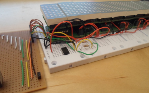
When driven via USB it was only really possible to drive 2-3 LED matrices at a decent refresh rate, but with a microcontroller all nine in a row could be driven without very obvious flicker. The LED matrix dots were not quite as bright as I would have liked, but lower-valued protective resisitors on the LED modules could sort that issue out. While doing a complete update of the display data via RS232 is not quite seamless, I feel it is good considering the limitations, and it can be concealed using work-arounds.LED matrix mounting
With the RS232 interface, this whole set of circuitry is a self-contained unit, so I was planning on making a “permanent” base for the LED display, but as it turned out using small solderless breadboards was actually the cheapest & easiest option for a secure mounting. I had also ordered in some thin PCBs to take care of the address allocation, but as can be seen I just used wires instead, as the PCBs have yet to arrive. I suspect that the joined-together breadboards put a bit of strain on the PCBs, so am considering alternatives such as smaller breadboards stuck to a piece of hardboard.Use of I2C
While I predictably reverse my previous conclusion that I2C is unsuitable for high-speed refreshes, my feeling is that the 100KHz clock rate is right on the margin for the task at hand. If it wasn't for the limited address space that restricts the PCF8574 I/O expanders to a maximum of eight on the same I2C bus, I probably would have created a display long enough to have the nasty flicker that plagued the USB-driven display, whereas with the 9-matrix display it is only just noticeable. On the whole using I2C was good from an experimentation view-point, and the approach is architecturally sound.Microcontroller limits
I was originally going to use thePIC12F1822 microcontroller but the compiler was not able to fit all the state variables in the limited amount of RAM, so instead I used PIC12F1840. This highlighted a balance between the generous provision for program code alongside the highly limited run-time state available, which meant implementing code in a very different way to what is considered “good practice” on desktop systems. Basically I made use of straight-line program code with hard-coded variables everywhere, rather than my normal practice of having a short loop with parameters kept within an array. The SDCC C compiler is also something of a rough diamond compared to the likes of GCC and Clang.