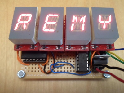
17-segment LED mainboard
25 November 2018For three months the 17-segment LED modules I made have been sitting unused on my desk, and I thought it was finally time to make a main-board for them. Making use of only components I already had in stock it was a mini-project lasting a few days, and using strip-board it was a project that was very much unplanned. Ideally I would have liked it to be more than four digits wide, but overall I am happy with the results.
Circuit design
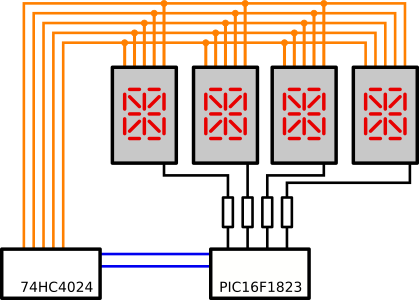
The LED modules themselves have on-board decoding so that the active segment is signalled using five pins rather than the seventeen of the LED chip itself. These pins connect to a common bus that is in turn driven by a74HC4024 ripple counter, so the active segment selection cycling is ultimately controlled using only two micro-controller connections: Count-advance and reset. The drain pins (i.e. the LED chip common-cathodes) are controlled directly by the PIC16F1823 micro-controller. This is summarised in the schematic below:
Prototyping board
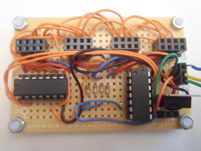
The deciding factor of what prototyping board to use was the connectors for the LED modules — strip-board was not suitable because cutting a track involves drilling out an entire hole, which would have been a headache with the 8-pin receptacles. The only perf-board I had in stock was the 4cm-by-7cm MulticompMC01007 that I used once before for a 555-based sounder circuit, and if I had any left in stock I would have opted for 10cm-by-10cm MC001796 instead — the MC01007 turned out to be a tight fit, as can be seen below. As is a common theme when using LED chips a lot of the effort is just wiring up, although the use of the LED modules rather than the LED chips directly did greatly reduce the total amount of wiring needed.
Ripple counter
The counter is a TICD74HC4024E, which is a 7-bit ripple counter, although only 5 of the counter outputs are used. Control is basic — just increment and reset — but for this circuit that is all that is needed. Inputs and outputs are all buffered, so the inputs draw minimal currents, but the outputs are capable of 25mA each or a total of 50mA — not that the latter matters as it is the decoders on the LED modules themselves that supply the LED chip power. In hindsight it may have been better to sacrifice support for the decimal-point and instead connect the lower four segment control lines directly to the micro-controller.
Micro-controller
ThePIC16F1823 is basically a PIC12F1822 with an extra 6-pin port — the latter has been a favoured chip of mine for some time, so I decided a while ago to stock the F1823 variant. At 14 pins it is the same physical size as the PIC16F630, which makes it a little limited in terms of GPIO capability, but is much more versatile having among other things, I2C support. The original plan was to include an in-circuit programming header, but in the end space constraints prevented this.
Module drain resistors
When I made the LED modules I decided that current-control should be deferred to an external driving circuit, rather than having any on-board resistors. This was partly due to space on the module PCB, and partly to put off having to work out what current to allow, but being a complete circuit resistors had to be selected to limit the current draw. I was originally going to use 390Ω but in the end opted for 1kΩ due to their smaller physical size. I have no regrets in this conservative choice of current-limiting resistance.I2C pull-up resisitors
Conspicuous by their absence is I2C pull-up resistors on the SDA and SCL lines. While there is room for them to be squeezed in, the circuit has wires all over the place as-is, and since I was testing using an I2C master that has built-in pull-ups I did not feel the need to do so. A bad habit admittedly, but I decided to let it slides since this was a circuit intended to fill in the time rather than be used in the longer term.Firmware
Although influenced by the firmware for the earlier 17-segment display that used thePSC05-11CGKWA LED chips directly, the firmware for this display is mostly rewritten due to the off-loaded segment cycling and the use of a different microcontroller. The (unreleased) Python script that was used to construct the segment lookup tables had provision for differences in the order that segments are lit, so it was reused to generate the lookup table in this firmware. As with the previous display, the firmware is available in Bitbucket, and some firmware design issues are covered in the following sub-sections.
Clock speed and Timer2 delays
With the microcontroller running at 500kHz clock speed and Timer2 using 1:1 for pre-scale & post-scale, both clock increments and most instructions will take 8μs. This means a total refresh time of 25ms equates to 3,125 instructions, which in turn requires the Timer2 period to be 183 or less, but using this value there was noticeable flicker. A value of 156 — which corresponds to a refresh time of 20ms — had no obvious problems with flickering. A quick test running the code in gpsim showed that a whole refresh took 2,199 instructions, which works out at 137 per segment, so the segment blink time is not far off the time it takes to process a switch-over. This implies that 500kHz, which is the highest clock rate for the medium-frequency oscillator within the microcontroller, is a bit marginal.Code efficiency
The firmware for this display makes use of optimisations that were investigated for the firmware used by the LED Matrix tile, namely the manual loop unrolling used in thesegsClear() and the expanding out of segsFlip(), and the background of these optimisations is explained in that article. Some of the other functions are implemented in both C and inline assembly, to see whether significant amounts of extra speed can be wrung out of the firmware, but for the refresh code-path it looks like the gains are minimal. I also partly implemented the entire firmware in assembly, but will discuss the latter in a future article.
Final words
This mini-project only took up a few days and was actually completed at the start of November, but due to cross-references to yesterday's article which in itself got held up due to a second revision of the PCB being ordered, publication of this write-up got delayed. Even with this delay I decided to defer the rewriting of the firmware in assembly to its own article, because the circuit itself was a quick just-for-fun mini-project, whereas an all-assembly firmware is going to bring up a load of issues that would cause this article to lose focus.
I feel that the 15-by-25 MC01007 perfboard is a nice size for a circuit — the smaller 15-by-15 hole MC01006 I came across earlier is only really enough space for a single chip and even then things at times left a little tight, whereas the extra 150 holes allows two chips. However it still limits circuit size to what can realistically be soldered up in an afternoon — the next size up is 37-by-38 hole (10cm by 10cm) MC001796 which is for a size of circuit that needs planning rather than spontaneously. For such circuits I prefer stripboard.