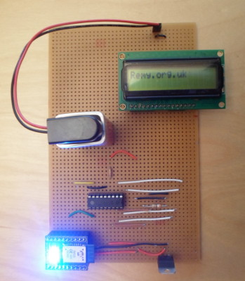
Bluetooth-driven LCD display
24 December 2017For this project I created an LCD display that could be updated from a mobile phone via a Bluetooth connection. I made use of the RN4020 BLE chip (Farnell 2442930) which I ordered in ready-mounted on a breakout board, although the way I used the chip is not particularly sophisticated. Like my RS232-controlled LCD display, this particular project was something of a longer-term ambition I finally got round to building.
Compared to other recent projects this board required more ad-hoc work than usual, and I certaily came close to abandoning it on more than one occasion. Most of the effort was down to various gotchas of which the root cause was components that do not operate at 3.3 volts, which sent me on various wild goose chases before I realised the specifications I was assuming were fiction. This had not been a problem in the past because for previous circuits I had standardised on 5 volts for Vcc.
Design choices
This project was intended as an applied-knowledge one rather than a learning excercise, so many of the design decisions were simply down to what components I had on stock seemed most suitable. These are elabored on below.- Circuit voltage
- In the past I have always used 5 volts when building circuits, although I am not sure why I originally standardised on this power level. However the RN4020 Bluetooth chip I was using is rated for a maximum of around 3.6 volts, so this time round I am instead using 3.3 volts for the whole circuit.
- Breadboard choice
- Because of the size of the space gap between the pin rows on the RN4020 breakout board, I thought the IC breadboard used in my last two projects would be impractical or at the very least a tight fit, so I was back to using stripboard. Compared to IC breadboard and PCBs, stripboard is something of a headache to use. The main problem is routing power connections, followed by the need to plan out track cutting. With the IC breadboard I wad able to skip doing a schematic, but getting a stripboard layout right requires that extra layer of validation.
- In-circuit flashing
- I was wavering whether to go to the effort of including an in-circuit flashing socket, because it would have to be located in a position that would require a lot of track drilling and long wires. I was doubtful that the expected firmware writing effort justified the provisioning of a programming port, but ultimately left it out as flashing the
PIC16F88chips (later replaced) would still need an external 5volt power supply.- Choice of microcontroller
- Although I later switched to a low-power variant, I opted for the
PIC16F88because I had a stock of them, and expected that I could mostly re-use the firmware from my previous project. - I was wavering whether to go to the effort of including an in-circuit flashing socket, because it would have to be located in a position that would require a lot of track drilling and long wires. I was doubtful that the expected firmware writing effort justified the provisioning of a programming port, but ultimately left it out as flashing the
The gotchas, in order
Although I hacked around a lot with this particular board, doing rework of which some was subsequently reversed, the final circuit is not that far off the original design. I got away with the ad-hoc modifications because very few of the tracks were shared — pretty much all the track drilling was between the two RL4020 headers in the top-right corner — and the board as a whole had things spread out a lot. However in the process there were quite a few things that made the building of this circuit a less-than-smooth process.Voltage regulator pins
The 5volt regulators I normally use have the ground pin in the middle but the 3.3 volt regulators have ground at the far right. More annoyingly the ground and voltage in pins are not next to each other, something I normally take advantage of by soldering a 2-pin recepticle right next to the regulator. Thankfully it came to me that I should checked the pins just before I was about to solder in the regulator, and this was also before I had soldered in any wires. I had an unused track running the whole height of the board next to were the regulator was suppoed to go, so no major layout rework was required.LCD power requirements
When powering the circuit using a money-patched external 5volt power supply the LCD successfuly displayed a test message, but when using the 3.3volt regulator, nothing was shown. I concluded that the LCD displays I had in stock needed the full 5 volts to operate, so my original solution was to graft in a seperate 5volt regulator to power just the LCD display, but in hindsight this was destined not to work. I eventually removed this second regulator, undid the rework, and ordered in a 3volt-capable LCD display.LCD pin directions
Even though the 3 volt LCD display has the same pin numberings as the 5 volt variants, the latter of which was used to do the original breadboard layout, the pin numbering is in the opposite direction. As a result, rather than being nicely in the middle of the board, the LCD display was hanging off the bottom-left corner. I added in a second set of LCD recepticles further up the board which partly rectified the problem, although the text was upside-down compared to what I expected.PIC16F88 vs. PIC16LF88
After installing the 3v-capable LCD display I was trying to work out why it was just showing black squares rather than the expected test output, and I even went as far as ordering in another 3 volt display from a different vendor, in case it was a damaged unit. I eventually found out that the data-sheet was fibbing about the “wide operating voltage range” of thePIC16F88 — there is actually also a low power variant PIC16LF88 that can operate below 4 volts, but it is somewhat buried within the data-sheet, with the first indication coming on page 162. I suspect a similar gotcha is also why the 3v LCD panel did not work with my PIC16F630-based board hot-wired to a 3.3v supply.
For me this was a blow to the trust that can be placed in data-sheets, which in the past I treated as unquestioned gospel. Now I realise that they, at least on the front pages, are marketing documents.
To make matters worse, even though the PIC16LF88 can operate on as low as circa 2 volts, it seems that its brown-out reset has to be specifically disabled because it always uses a threshold of around 4 volts. Maybe I just got a bad impression when actually problems were elsewhere, but there also seem to be issues with the startup & watchdog timers, at least at lower voltages. I never got round to working out whether PIC16F88 and PIC16LF88 firmware is fully interchangeable.
RS232 TTL voltage issues
Before putting together the microcontroller and the Bluetooth chips I hooked up a TTL-level RS232 adapter for testing purposes. The adapter is supposed to be 3.3 volts, and the Bluetooth chip itself was fine with it, but for some reason thePIC16LF88 did not like being connected to the adapter's transmit pin. After much banging of head against desk I made a potential divider on the hunch that the adapter was actually using 5 volts TTL, and all the problems suddenly disappeared. Maybe it was too much current rather than voltage, but I never had such a problem with the 5 volt variants.
Firmware development
Functionally the only real difference between this circuit and my previous RS232-driven LCD is that the UART connection is a Bluetooth chip rather than an RS232 voltage driver. As a result it used the same firmware, but with modified command parsing. In short it looked for the following command, where<value> is a hexadecimal representation of the new text characters.
WV,0018,<value>.
All other commands coming over the UART are ignored. By any measure this is something of a wall-banger, particularly as actual setup of the Bluetoot module was done seperately via a PC. The RN4020 module can run simple scripts that include being able to perform I2C transactions as a master, but the scripting features available at a glance did not seem to be of use in this particular case. Although at various stages I suspected that the 3-volt LCD displays need longer delays than the 5-volt ones, experimentation eventually eliminated this as as an issue.
Remarks
Much of the ordeal with this circuit was the extent that a lot of 5-volt components simply will not work with 3.3 volts, even when it is implied in official documentation that they will. The most troubling issue is that I suspect that my 3.3 volt TTL-level RS232 adapter might actually be operating at 5 volts, or at least behaving in a way that is unexpected given my experience with 5-volt circuits. This circuit was supposed to use just things I had in stock, but in the process of tracking down the problems I bought in something like €50 of new stuff, a good portion of which I have doubts whether I will ever use.On the plus side, apart from a mis-pinning of the voltage regulator, the final circuit is basically identical to the original design.A Bluetooth-controlled LCD display is another item ticked off my vanity to-do list, although I would have liked to have done it on a smaller board — this is the type of project I would consider showing off to others, so I can foresee redoing it on a smaller board.