PIC16F630 timer
11 November 2017The goal of this project was to create a timer circuit, and for various reasons I decided to base it around the
PIC16F630 microcontroller and use a small LCD display to show the time. In practice it would turn out to be a refinement of my previous LCD display project, which even though this was not the intention, was something I probably would have done sooner or later. I feel the main contribution of this article is understanding of the timers available in PIC16F630, rather than how the time is displayed.
In de-facto revisiting LCD displays, which was something that pulled me towards electronics in the first place, I got a feel of how much I had advanced in understanding. Three months ago just getting output to display at all was fulfilling an ambition with a lot of history behind it, but now I consider it to be part of a larger goal. It also feels a nice diversion from all the LED pulsing of the last few months. I had considered LED displays for the time display, but the practicalities felt too much like stuff I had done recently.
Choice of display
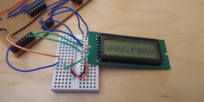
Originally I was going to use 7-segment LED modules for the digit display, but instead I opted to use a small 8x2 LCD display, because using the 7-segment LEDs very quickly looked like it would end up being a re-run of all the work that went into my LED matrix display. I also wanted to use up my stock ofPIC16F630 chips, but as things turned out I ended up buying in more stock, as well as try out a new stock of bread-boards I had recently obtained. The small LCD display is a Midas MC10808A6W-SPR-V2 (Farnell 2675573), which is a HD44780 based display much like that used in my DEM16217 LCD display project, and with a little rewiring even ran from the same circuit:
As a result of this I was able to re-use the design used to drive the DEM16217, because this time round I wanted the effort to be on the timing routines rather than on getting the display working. However I felt the original display project was a bit of an experimental bodge in which I was just interested in getting things working, so this time round I made a few simplifications & improvements:
- Tied the Read/Write pin to ground
- In theory it was possible to read the LCD busy state, but in practice it never seemed to work. This time round I simply hard-wired the read/write to always be write, accepting that I would rely entirely on delays in the firmware code.
- Fixed the contrast pin V0 value
- Contrast control never really worked as advertised — I had tried making a fixed potential-divider out of resistors, but getting things to show involved instead attaching the pin to just ground. In the end I decided to use a strong pull-down (390Ω) rather than a direct attachment, but having the resistor did not seem to make much difference.
- Refined LCD delays
- The delays in the previous project were excessive, as only a few operations — mainly used on start-up — needed to be of the order of milliseconds, so I changed them to delays nearer what was actually required for individual operations. In the process I also used a cleaner approach to implementing the waits.
- Changed the mode-switch routine
- The start-up procedure was not entirely reliable in getting the LCD display into 4-bit mode, so it sometimes failed. This fault was rectified.
Gpsim design
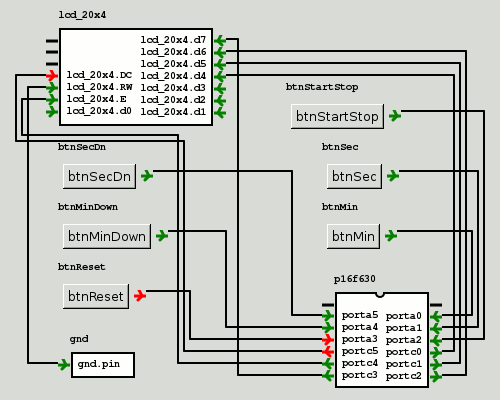
Although I was building the hardware, I was expecting much of the effort to be in writing the firmware, so I constructed an equivalent circuit in gpsim for this purpose. It is in fact the layout from the previous LCD project, modified to add buttons, although not all the button functions were implemented in the end. One annoying feature of the buttons is that they were toggle rather than press-to-make, but in itself this was not a major problem.
I have been critical of gpsim recently due to the number of bugs I unearthed, but in this case I consider it to be an uncompromising help to what I was trying to achieve. Without it I doubt I would have made such rapid progress, and anyone reading this article would have to buy hardware to actually try out the stuff mentioned.
Reliability of the PIC16F630
Although the purpose of this project was to try and use up the stock ofPIC16F630 microcontrollers I had bought a few months back, I finally concluded that they are simply too unreliable and ended up buying a new stock from Farnell. The existing stock was mostly ordered from China, and at the very least I suspect a few were equipped with some sort of non-erasable (or at least, non-electrically erasable, such as EPROM) flash memory. I also suspect some may only have been 3.3volt tolerant, and/or possibly damaged in transit. Whatever the cause, they seemed to be a constant headache in a way none of the other PIC microcontrollers I had used were.
To be fair almost all the other stuff I ordered from China over E-bay has turned out fine, but integrated circuits specifically have been an almost universal disaster. The price saving is simply not worth either the problems or the shipping lead-time — assuming they arrive at all. They might just about be OK for a production run when a faulty unit can easily be spotted, but for development & experimentation when tolerances are likely to be stressed they are not worth the hassle.
Support functions
Rather than giving one long code listing, I broke the firmware down into more sub-functions than strictly required, so I could explain the specifics of each. I omitted a few minor functions such asincSecond() & setAlarm(), but the absence of these functions should not affect the understanding I am trying to present. The actual focus is on timer control and correct LCD signalling.
Delay routines
For my previous LCD project I used a single delay for all LCD operations, and by any measure it was too long. This time round I deciced to have two delays, as not all operations need a long processing delay. For the longer delay I decided to use the Timer0 module, which made use of actual timing circuitry, rather than using nested busy-loops.void delayLCDSetup(void) { INTCON &= ~0b100000; TMR0=245; INTCON &= ~0b100; INTCON |= 0b100000; while(!(INTCON & 0b100)); INTCON &= ~0b100000; }
When the timer is running TMR0 gets incremented, and the interrupt flag gets set when it wraps around from 255 to zero, so most of the time in this fucntion is in the empty loop that constantly checks for the interrupt. The bottom three bits of OPTION_REG set the frequency-division of the input into Timer0, and the highest value of 0b111 corresponds to 256us per increment (the PIC16F630 has a fixed & calibrated internal clock of 4MHz).
Previously I used nested loops — the limited PIC data-types meant a single loop would not last long enough — written in C, but working out how long the loop actually lasted meant looking atthe compiled assembly code, which was littered with instructions that weren't strictly required. For the much shorter LCD write delay I decided to still use a busy-loop, but to write it in inline assembly from the start to make it more “predictable”:
UsingMOVLW 249 would result in a delay of 1ms, which is close to the upper limit of what this loop can do due to the 8-bit word size, but delays of this length is where I prefer to make use of timer interrupts rather than busy loops. The loop parameter iTic has to be a global variable, but SDCC conveniently makes it available using the macro _iTic.
LCD interface writes
Using 4-bit mode is more work, but it means using less wires, and in any case it is the mode I got things working with in the first place. For display writes, the letter is split up into nibbles and put on the wires in the required order:void lcdWrite4(unsigned char letter) { unsigned char lo = letter & 0b1111; unsigned char hi = letter >> 4; PORTC=0b110000 | hi; delayLCD(); PORTC=0b100000 | hi; delayLCD(); PORTC=0b110000 | lo; delayLCD(); PORTC=0b100000 | lo; delayLCD(); }
For other operations I assume the calling code just provides the required nibble, as typically these will be hard-coded constants:
void lcdBangNibble(unsigned char bits) { PORTC=0b010000 | bits; delayLCDSetup(); PORTC=0b000000 | bits; delayLCDSetup(); }
LCD startup
Although I think only some of these operations need the full 1ms delay oflcdBangNibble(), the extra wait does not matter for a one-off startup procedure. The main trick is forcing the LCD display into 8-bit mode, a trick I pinched off Wikipedia, so that the switch to 4-bit mode is from a known state.
void lcdStart(void) { // Ensure 8-bit mode, then set 4-bit mode lcdBangNibble(0b0011); lcdBangNibble(0b0011); lcdBangNibble(0b0011); lcdBangNibble(0b0010); lcdBangNibble(0b0010); lcdBangNibble(0b1000); // Display on, Clear, Entry mode lcdBangNibble(0b0000); lcdBangNibble(0b1100); lcdBangNibble(0b0000); lcdBangNibble(0b0001); lcdBangNibble(0b0000); lcdBangNibble(0b0110); }
LCD time display
The update of the LCD display is done by performing a carriage-return and then overwrites the old values with new ones. I don't think SDCC provides any sort of string formatting functions such as printf(), so some trickery is needed to calculate the character value to write:void lcdUpdate(void) { lcdBangNibble(0b0000); lcdBangNibble(0b0010); lcdWrite4(' '); lcdWrite4('0' + (valMin / 10) ); lcdWrite4('0' + (valMin % 10) ); lcdWrite4(':'); lcdWrite4('0' + (valSec / 10) ); lcdWrite4('0' + (valSec % 10) ); lcdWrite4(' '); }
Higher-resolution timing
Whereas Timer0 is used for LCD delays, the much higher-resolution Timer1 is used for delays related to button presses and actual timing. The resolution of this timer — independent of Timer0 — is set by two bits within theT1CON register, and here the maximum 0b11 (division by 8) is used. When a button is pressed, the a timeout is set using the following function.
void setButtonTimeout(unsigned char hiTics) { T1CON &= ~0b1; TMR1H=255-hiTics; TMR1L=0; PIR1 &= ~0b1; PIE1 |= 0b1; //TMR1E T1CON |= 0b1; }
The handling of button presses consists of a race between the button being released, and the timeout interrupt from Timer1 occuring. If the button has been released — detected by a pin-change interrupt and then checking the relevant pin itself — the timer is cancelled. Otherwise a new timeout is set and the return value indicates a time-based increment/decrement should occur.
char checkRelease(unsigned char btnMask) { if( INTCON & 0b1 ) { if(! (PORTA & btnMask) ) { valMode = 0; T1CON &= ~0b1; } INTCON &= ~0b1; //RAIF } if( PIR1 & 0b1 ) { setButtonTimeout(0x80); return 1; } return 0; }
When actually counting down real time, the following is used which sets a nominal 500ms timeout — on hardware it might need adjusting using experimentation. This is close to the upper limit of what the timer can count, as the combined values of TMR1H & TMR1H are 0x0bdd, and the timer increments this value.
Startup pin-check
I added this as a sanity check for debugging purposes, as unlike simulation actual hardware is somewhat unforgiving to the absence of pull-up and pull-down resistors, and it helps narrow the problem down to a floating pin. If not all the input pins are held low, it dumps thePORTA status to the display.
void waitPinsReady(void) { valMin = 180; // Renders as B0:00 while(1) { valSec = PORTA; if(valSec == 0) break; //valMin++; lcdUpdate(); } valMin = 0; }
Main firmware entrypint
The main body of code is mainly a state-machine and is really only included for completeness as all the interesting things are delegated to functions shown above. It is not as robust as it could be, most notably to pressing multiple buttons at once, because such robustness if beyond the scope of this article. I had considered using interrupt handlers, but splitting interrupt processing between those that are checked from the main code body and those that are handled in a call-back simply over-complicated the design. I opted for checking of interrupt flags within the main body of the firmware because it is an event-based approach I am used to, and it got around the course-grained options for choosing what interrupt flags cause an actual interrupt call-back.#define NO_BIT_DEFINES #include "pic16f630.h" __code short __at (_CONFIG) cfg0 = _FOSC_INTRCIO & _WDT_OFF & _MCLRE_OFF & _PWRTE_OFF & _CP_OFF & _CPD_OFF; unsigned char valMin = 0; unsigned char valSec = 0; unsigned char valTics = 0; unsigned char valMode = 0; /* Functions from above would go here.. */ void main(void) { CMCON = 0b111; TRISA = 0b111111; TRISC = 0b000000; OPTION_REG = 0b00000111; T1CON = 0b00110000; lcdStart(); waitPinsReady(); lcdUpdate(); // Interrupt on change for all PORTA pins INTCON &= ~0b1; IOCA = 0b111111; INTCON |= 0b00001000; while(1) { // Idle state if( valMode == 0 ) { if( INTCON & 0b1 ) { if( PORTA & 0b1 ) { incMinute(); valMode = 2; setButtonTimeout(0xff); } else if( PORTA & 0b10 ) { incSecond(); valMode = 1; setButtonTimeout(0xff); } else if( PORTA & 0b100 ) { valMode = 100; setTicTimeout(); valTics = 0; valStartReleased = 0; } else if( PORTA & 0b10000 ) { decMinute(); valMode = 4; setButtonTimeout(0xff); } else if( PORTA & 0b100000 ) { decSecond(); valMode = 3; setButtonTimeout(0xff); } lcdUpdate(); INTCON &= ~0b1; } } // Button being held down. Periodic increment/decrement. if( valMode == 1 ) { if( checkRelease(0b10) ) { incSecond(); lcdUpdate(); } } if( valMode == 2 ) { if( checkRelease(0b10) ) { incMinute(); lcdUpdate(); } } if( valMode == 3 ) { if( checkRelease(0b10) ) { decSecond(); lcdUpdate(); } } if( valMode == 4 ) { if( checkRelease(0b10) ) { decMinute(); lcdUpdate(); } } } // Countdown active state if( valMode == 100 ) { if( PIR1 & 0b1 ) { if( valTics == 0 ) valTics++; else { if( valSec == 0 ) { if( valMin == 0 ) { setAlarm(); } else { valMin--; valSec = 59; } } else valSec--; lcdUpdate(); valTics = 0; } setTicTimeout(); } if( INTCON & 0b1 ) { // Assume no other button is pressed before start/stop // is released, otherwise the timer deactivate below // will not be due to start/stop being released.. if( PORTA & 0b100 ) { valMode = 0; T1CON &= ~0b1; } INTCON &= ~0b1; } } } /* while(1) */ }
The (almost) completed board
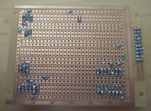
This project would have only taken 2-3 days but it was beset with problems, some of which were due to dodgy micocontroller chips, and others due to the poor soldering characteristics of the wire I was using. The board is shown below, top-side to the left without the LCD display in place so the wiring can be seen, and under-side to the right. I took less up-front care with this board than previous ones, but I think the only fundamental fault was the bare ends of some of the brown wires.
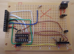
My original intention was to attach buttons directly onto the circuit board, but I never got round to this, and instead I added receptacles for the input pins that were not already connected via the reprogramming port. This is somewhat ugly, but by this point I thought the circuit may have problems, so that any further additions should be done in terms of expedience rather than attractiveness. On more than one occasion I had come close to discarding this board and starting over, but in the end traced problems to elsewhere. Below is picture of the circuit in full working order.
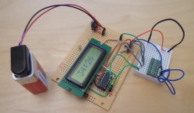
The white breadboard contains pull-down resistors (using my SMD resistor array), and I used a fly-lead attached to Vcc rather than wiring up some buttons — for some reason obtaining push-to-make buttons is a lot harder and more expensive than it should be, and I decided not to let a lack of them hold this project back. In any case the focus of this project was on the firmware rather than the hardware, so although it was not complete in the sense of having buttons to press, it was functionally complete.
Remarks
This started out as an excuse in trying out a new breadboard, but in the end turned into a re-run of an earlier display project. It was helped by having a working circuit as reference, which allowed me to take a few short-cuts compared to my previous circuit design process, but it also meant restocking hardware I did not really want to restock. Below are various remarks regarding what I got out of this mini-project.- IC Breadboard
- The breadboard was nice in terms of not having to drill out tracks, but on the whole it was that bit disappointing. I knew that the wires I was using are poorly suited for soldering, but they seemed notably problematic with this board compared to be usual strip-board. This board is advertised for use with integrated circuits, but it could really have been 5 holes taller, allowing for three rows of chips rather than two. This was one thing that put me off using 7-segment LEDs.
- Pull-up resistors
- The PIC16F630 does not seem to have any internal pull-up on the MCLR pin, and not having an external pull-up was a source of all sorts of problems with my earlier firmwares that still had MCLR set to the default enabled. Even though I disabled MCLR to allow a sixth input, I did not use the extra button in the end, and my inclination is to avoid using the pin anyway. More generally actual hardware (unlike simulations) is very unforgiving to floating inputs, leading to all sorts of strange results, which did not really affect me in the past as this is the first circuit I made that actually uses input pins.
- Accuracy
- As an initial test I compared the timer — both simulated and flashed to hardware — to a 50-minute countdown on a stop-watch. Under gpsim simulation it was reasonably accurate, but the hardware was fast completing the countdown in around 46 minutes. I rectified this by adjusting the values in
setTicTimeout(), but it was somewhat trial-and-error. The chip clock is supposedly calibrated to quite tight margins, so the initial margin of error of almost 10% surprised me. - As an initial test I compared the timer — both simulated and flashed to hardware — to a 50-minute countdown on a stop-watch. Under gpsim simulation it was reasonably accurate, but the hardware was fast completing the countdown in around 46 minutes. I rectified this by adjusting the values in