NXP USB Firmware
13 November 2020Getting native USB working on the NXP
LPC11Uxx series of ARM Cortex-M0 chips has been an ongoing project of mine since August 2019, although it was only the start of this year that I made any significant progress with writing the firmware.
The project was plagued with uncertainty over whether the mini development board I made for myself was fit for purpose, and in the end I got through three revisions of the PCB.
This article covers my experiences in finally getting the firmware to the stage where Linux is able to enumerate the chip and it appears when using lsusb — a future article will cover doing something useful with the hardware.
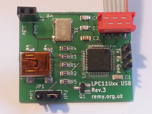
Development hardware
One of the major headaches with this project was that I had to build my own hardware before I could develop the firmware, and for the benefit of others I have released the PCB design files for the one I used to compliement the firmware release. Although there are off-the-shelf evaluation boards for theLPC11U24 I don't think they are still available and in any case evaluation boards tends to be grossly over-priced for what they are.
The first revision of my hardware was sent for fabrication mid-2019 although I am not sure when I got round to soldering the PCB.
I went to to make a second revision in Feburary 2020 and third revision in August, although the latter was about miniaturisation and minimalisation rather than fixing show-stoppers.
The third and final revision was open-sourced even though its ability to switch between high- and low-speed would prove to be useless.
Sources of information
I did make some references to the LPC Library samples to work out specific tricks but otherwise my own implementation presented here was written from scratch based on theLPC11Uxx data-sheets and user manual.
My intention was to make a firmware targeting a specific chips that is stripped down to the bare essentials rather than an all-in framework that makes it hard to see the basics.
While doing this project I also was trying to get USB working on the Microchip PIC16F1454 and the different perspective the latter's data-sheet used to explain things helped fill in a few knowledge gaps.
A few posts on NXP's help forums also helped with specific pit-falls.
A major source of problems is that while sources such as USB in a nut-shell give an understanding of how the USB protocol works at a conceptual level, there are still significant differences with how hardware itself presents the control interfaces for USB functionality. For instance I spent a long time trying to work out how firmware indicates when a NACK should be sent, but hardware does not actually have a register flags for indicating such a thing — hardware does this implicitly when an end-point is not setup to handle data.
Firmware development
The USB handling firmware I wrote is intentionally minimalist and at time of publication does just enough for the device to be enumerated by Linux — at some point in the future I will use libUSB to interface with the hardware. There is minimal error checking and I am in no doubt things that should be done are omitted, but my view is that it is best to start with something that is stripped right down to bare-bones, and then add things in once things have been sussed out. I made a simplifying assumption that all control data all fits within a single 64-byte packet so the vast majority of the actual processing is in response to receiving a setup packet. Most debugging was done using a combination of Wireshark to decode and display the USB request and response packets, and using the RS232 interface as a side-channel for printing out internal state.Setting up the end-point tables
Data payload and end-point configuration information is specified in an area of memory that is then passed to the USB module via registers. This memory has to be aligned and I initially did some trickery using things like__attribute__((aligned(256))) but then I found a dedicated USB RAM area starting at 0x20004000 that is happily segregated from the rest of the data memory and I suspect is deliberately placed higher in the address space in order to avoid headaches with the split way data buffers are pointed to.
I am not sure if there is anything special about the address range of whether it is just some ordinary memory that just happens to be intended for use with USB.
The way these data buffers are specified in the end-point tables is a recipe for mistakes: The upper bits are common and specified via a register; the middle bits are given in the table; and the lower bits are all zero since the table assumes 64-byte blocks. I wrote a bunch of access functions that did pointer arithmetic into this block, and one thing I frequently did earlier on in development was going back over these functions to make sure they were correct.
Getting chip clocking right
Getting the parameters for the chip clocking right was something that actually proved quite tricky, probably not helped by switching between development hardware that required different parameters and forgetting to change then. For some reason getting clocking parameters wrong did not prevent the RS232 module used as a debugging side-channel from working but it did subtly screw up USB transactions, which caught me out as I did not think to check the clock speed until I had checked a load of other things first. Some combinations of clock settings also did not seem to work as documented, but in hindsight some of this may have been the result of the mistaken belief that low-speed was supported.For simplicity I used an external 16MHz oscillator and enabled the phase-locked loop clocking for both the main clock and the USB itself, as this allows both to use the same parameters. External clocking is required to use USB and this can actually simplify things because a lot of the internal circuitry is simply by-passed. For some reason switching between phase-locked loop sources requires register bits to be toggled rather than just set/cleared.
Vendor & product ID
One issue that needs to be addressed is what USB vendor and product id number to use, as normally obtaining a vendor id comes with a price tag of $6,000 and may not be transferred or sub-assigned. However there is PID.codes which has the vendor id0x1209 which long story short was owned by a company that has now been dissolved, and they donated their entire registration for open-source use. This particular vendor id is one that was originally obtained before the rules that otherwise de-facto disallow open-source use were introduced and hence has been grandfathered.
It seems that as long as the firmware & hardware for a device are open-source a request for a product id is unlikely to be rejected. However they have a reserved range 0x0001 to 0x0010 which have been set aside for testing purposes, so one of these is used by my firmware.
Setting the device address
For some reason assigning of a device address as part of the SET_ADDRESS setup only works if the enable bit is set at the same time as the address bits within theREG_USB_DEVCMDSTAT register.
This stumped me for a significant length of time as I saw no reason why this should be the case and it is not mentioned anywhere in the reference manual.
Another pit-fall with setting the address is that it cannot simply be stuffed into this register as soon as it is known, as the device still needs to respond to the boot-strap address of zero — instead it has to wait for a device-to-host signal and then set it.
Closing remarks
When I first looked at USB support I questioned whether it was really worth the effort compared to using RS232 with an RS232-USB converter since all I wanted to do was pass arrays of bytes, and not concern myself with the overheads that USB had on top of just reading/writing/dev/ttyUSB0.
It was after some exposure to USB as part of my day-job that I decided to give USB a serious try-out, and having already worked out I2C and RS232 for several different microcontroller chips figuring out USB was my final frontier of firmware development.