7-segment LED display
22 December 2017This circuit provides a four-number 7-segment LED display which is controlled via an I2C interface. It was originally intended to be a 7-segment LED version of my LCD-based timer, but as due to how things turned out was scope-reduced to just being an I2C-driven clock display, with the timing functionality omitted. Most of the work was done over 2 days, and this was in part an exercise in seeing how I would cope with tightly-packed boards.
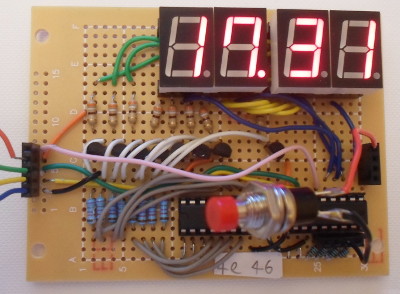
The original plan was to have everything on a single board, but as things turned out it was that bit too small to squeeze everything onto, and this board ended up being an I2C-driven LED display and button panel. Functionally it mirrors the basic design of my previous LED matrix display, with segments being powered by a current source and LED chip grounds being controlled by a current sink, each of which is driven by a seperate I/O Expander. The design choices made in the process of building it are detailed below:-
- LED recepticles
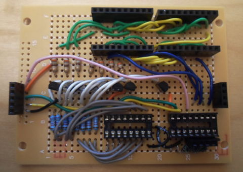
- Although the use of receptacle headers in the top-right means that the LED modules (Farnell 2627645) are not permanently attached to the board, the primary purpose of using them is to provide clearance for the wires below. Given limited space, putting wires underneath the LED modules was a necessity.
- Voltage level
- I settled on my usual 5 volts for the circuit Vcc because that is what most of the components I had in stock are rated to use, although as-built this circuit will also operate at 3.3 volts.
- LED protective resistance
- I opted to use 390Ω resistors to limit the LED segment current because it is a standard value I use with LED, and hence have a large quantity of them in stock. The 12.8mA they would allow was a bit over half the 20mA the data-sheet recommended, although it was not clear whether the latter was per-module or per-segment. It was something I decided not to put much thought into at the time, although in hindsight I suspect it is per-chip.
- Transistor base resistance
- From what I could make out from the data-sheet, the PNP transistors have a gain of around 150 with collector currents in the 10mA ball-park, so I opted for a base current of 0.1μ which would have allowed 15mA to flow through the LED modules. However the nearest value of resistor I had was 78.8kΩ which nominally would have only allowed a nominal collector current of xxxx, but in practice I could not tell any difference in brightness.
- Use of I/O Expanders
- The inputs to the PNP transistors and the ground pins from the LED modules require current sinks and the original plan was to use NPN transistors, but since it became apparent there was not enough room for them, I instead used two PCF9574 expanders due to them having open-collector output. It is supposed to sink a maximum of 10mA per pin, although I was not aware of this when I designed the circuit.
- Button headers
- The four pins on the right-hand expander that are not used as LED chip current sinks are used as connections for user-input buttons, and these have 2kΩ pull-up resistors attached, the intention being that button presses ground the pins. The choice of pull-up over pull-down was due to where power rails ran, and I opted for 2kΩ resistors due to the small size of the ones I had in stock.
Reading button input
ThePCF8574 does not have any internal configuration state and all eight pins are read/written at the same time. However on a write any pins that are intended to be inputs have to be set high, which for the open-collector output means the “off” state of high-impedence. In practice means the corresponding bit in the data byte needs to be set to 1 — if it is set to zero, the subsequent read will get this value regardless of what the input is.
For reasons I was not able to trace, reading did not work in a lot of circumstances I expected it to, most notably if the output-only expander was also being written to. With just the commands for the one expander being sent, all seems to work as expected. This seems to be the case even with the LED chips removed, so I don't think it is a simple issue of sinking too much current. I decided to forego programming a microcontroller to do the actual timing.
Driving from a PC
The following Python code will drive aUSB-ISS to output the I2C commands that will display 17.31 on the LED chips. For completeness it retains the button reading code, but it only seems to work properly if the first two i2cSend() calls within the innermost loop are removed. The USB-ISS can supply upto 80mA, so it is capable of powering the circuit.
#!/usr/bin/env python import serial,sys,time def i2cSend(addr, value): pkt = [chr(0x53),chr(addr),chr(value)] i2c.write(pkt) i2c.read(1) def i2cPoll(addr): pkt = [chr(0x53),chr(addr)] i2c.write(pkt) return ord(i2c.read(1)) listLED = [1,7,3,1] listDot = [False,True,False,False] # Upper bits output, lower bits input listChipBits = [0x7f,0xbf,0xdf,0xef] dictValues = { 0: 123, 1: 10, 2: 185, 3: 171, 4: 202, 5: 227, 6: 243, 7: 106, 8: 251, 9: 234, '.': 4 } if len(sys.argv) < 1: print "USAGE: {0} <tty>".format(sys.argv[0]) sys.exit(1) i2c = serial.Serial(sys.argv[1]) i2c.write([chr(x) for x in [0x5a,0x02,0x60,0x04]]) last = i2cPoll(0x47) & 0x0f try: while True: for idxChip in range(0,4): i2cSend(0x46,0xff) # All LED chips off ledValue = dictValues[listLED[idxChip]] if listDot[idxChip]: ledValue |= dictValues['.'] i2cSend(0x4e,ledValue^0xff) # Set segments i2cSend(0x46,listChipBits[idxChip]) # Next chip on time.sleep(0.0005) val = i2cPoll(0x47) & 0x0f if val != last: print "{0} -> {1}".format((last),(val)) last = val except KeyboardInterrupt: print "Ctrl-C" i2cSend(0x46,0xff)