Repairing Logitech M570 Trackball
12 April 2019Here is a brief overview of repairing a Logitech M570 trackball for which the mouse buttons are not acting as expected: Single presses either not registering or resulting in double-clicks, and spurious button releases & presses occurring when a button is actually being held down continually. The underlying fault is a worn-out tactile switch that needs to be replaced, which means desoldering the faulty switch and soldering in a replacement.
I am not sure which guide I followed the first time I did the repair work described below, but I suspect it may have been the IFixIt guide — one motive for writing my own guide is that I do not have to worry about it suddenly disappearing at some point in the future, and my own guide focuses on the bits that I think are the tricky stages.
Background
I have used Logitech trackballs since at least the mid-1990s, and the variant I currently use is the wireless Trackman M570 which I started using back in 2013 while I was over in New Zealand. At the time I preferred the wired Trackman Marble but for some reason it was no longer being made and the wireless M570 was the nearest equivalent that was still available. Unlike earlier trackballs that had problems with the ball wheels getting stuck the Marble and M570 used lasers, but five years of clicking evidently took their toll on the buttons. The problems first started with the M570 I keep with my laptop which I initially put down to it having also received quite a few knocks during various travels.At first it seemed like a random error dismissed as having given an unusually light press, but over the course of a month or so the faults got noticeably regular eventually it came to the point that they were interfering with work. In the end I had enough and replacing the button made all the problems disappear. Since then I replaced the other button and one of the buttons on my desktop trackball, although in the latter case the problem a lot more intermittent, and between these repair jobs I got a collection of pictures of most of the process.
The repair process
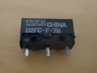
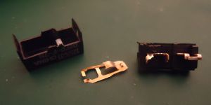
Button clicks are detected using an Omron D2FC-F-7N micro button, which is shown below, and I sourced some replacements off E-Bay — I assume it a commodity part but not knowing the differences I opted for a notionally identical replacement unit. Due to some bad experiences in the past I intentionally avoided listing that were ultra-cheap or had a non-EU seller, as this is one instance where quality is worth paying for.
Opening up the case
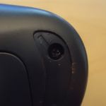
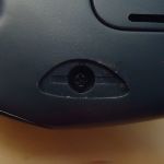
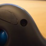
Opening the case requires removing a total of five screws, and four of them are shown in the picturs below: An easy-to-find one next to one of the anti-slip pads, and three that are underneath pads.
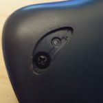
The fifth and final screw is the hardest to find — it is within the power battery compartment, and getting at it involves puncturing the label on top of it, as shown in the picture below. Given that the label carries a serial number I am guessing this is intended to detect user modification and hence void any warranty.
Removing the trackball caddy
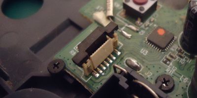
Before removing the trackball caddy it needs to be disconnected from the main PCB. To do this lift the black tab on the ribbon cable receptacle by about a millimeter or two, and then the ribbon cable will disconnect with ease. If you find that you are applying any force at all, it is still gripping the cable. The receptacle with the ribbon cable disconnected is shown in the picture below.
Removing the PCB
To remove the main PCB the raised daughter-board (top-left in picture below) has to be unscrewed, and then three further screws holding down the main PCB need to be removed. In the picture below one of the latter is out of sight underneath the daughter-board, and the other two are to the bottom of the image.
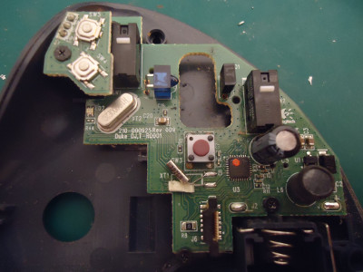
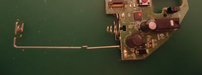
Once all four PCB screws have been removed the main PCB can be lifted from the casing, but take care with the wire that forms the electrical contacts for the battery compartment. This wire is shown in the picture below — you will need a pair of tweezers to ease out the far-left part that forms the positive contact for the battery.
Watch out for the switch
This is something I keep forgetting about — make sure that the external switch slider does not get lost, once the main PCB itself is removed there is nothing else holding it in place. Ideally you want the switch to be in the off position before removing the PCB, the reason of which will become clear during reassembly.
Desoldering the broken switch
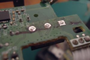
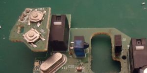
I think by far the hardest part of the whole repair process is de-soldering the faulty switch, and in practice I found it was next to impossible to remove the switch without breaking it. Aside from guessing that it is lead-free I have no idea what type of solder Logitech used in manufacturing, and I found that to melt it I had to set my soldering station to 400°C which is a lot higher than the 250-300°C I normally use for electronics work. Firstly I melted the solder that was surrounding the switch pins and sucked it up with a solder pump, and once this external solder was gone I clipped the wires so that they were flush with the PCB as shown below.
To remove the solder that is within the holes between the switch pin I alternated between using the solder pump after heating up the pins, and using desoldering braid. If you do not seem to be making any process it helps to add a little fresh solder to the solder joint — I am not sure why this helps, perhaps it is diluting the higher-temperature solder or perhaps it adds trace amounts of flux, but it seems to work. I found that it is very difficult to get the very last drop of solder out, so to finally get the switch loose I ended up heating the pins while pulling the switch with some pliars.
Once the faulty switch has has been freed from the PCB, a process that takes the majority of the total repair time, the rest of the repair job is relatively quick and easy.
A quick clean
Years of use meant the inside of the trackball was very dirty, most notably the scroll wheel, which had both grease stuck to the edge and gunk wrapped around the axle. The latter I removed using tweezers whereas the former I cleaned off using methylated spirits. A few blasts with compressed air also helps, but make sure all the screws are not loose on the table before doing this. It is not often these things are opened up, so it is worth taking the time to give it a proper clean.Soldering and reassembly
Once the faulty switch is removed all that needs to be done is for the replacement switch to be put into the vacated holes and soldered into place. Make sure you put the replacement switch in the right way round — the white button should be towards the top edge of the PCB. Once this is done reassembly is disassembly in reverse.
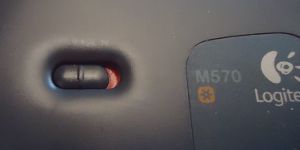
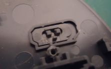
Check the power switch
When screwing the PCB back in place don't tighten the screws all the way, as the position of the external switch might not mesh with the power switch on the PCB — make sure it is in the off position before finally tightening up all the PCB screws. Looking from below the red “off” side of the switch should be visible and towards the inside of the trackball as shown below.