LCD dot-matrix display
17 September 2018This article deals the control of a MikroElektronika
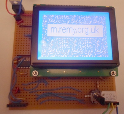
MIKROE-4 (Farnell 2361575) graphical LCD display which has 128x64 monochrome pixels. The display is based on two NT7108 display drivers, and is controlled via a parallel interface. This interface will be driven by a PIC16F1828 microcontroller, with display updates being received via an I2C connection.
Circuit design
The circuit is based around aPIC16F1828 microcontroller, which I recently decided to adopt as my go-to chip in favour of the PIC16F88, and following success with my second-generation LED matrix display decided to also include in-circuit flashing. Since the chip has both I2C and RS232 serial communications support, both are provisioned for via an external interface, although in the case of RS232 this provision is receive-only. Since the LCD display data-sheet recommends a variable resistor one is also included, although I am personally sceptical as to why one is needed, and would not be surprised if it ends up being removed in favour of fixed resistors. The circuit schematic is shown below.
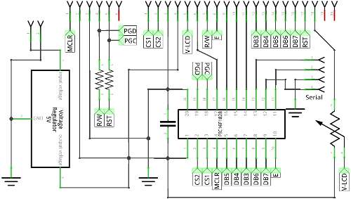
I decided to dedicate all the Port C pins to the LCD data bus, as Port C is the only port on this chip that support a full eight bits, and it makes logical sense to group them all together. I had wanted to use Port B for the LCD control lines, but these pins are required for serial communications, so it is the latter that this port is mostly used for. RB7 is used for the enable line as this is the one LCD control line that will always be toggled separately from the others, and it was free since I doubt that the chip would need RS232 transmit capability. I had also wanted to keep the in-circuit programming pins dedicated, but due to total availability of GPIO pins they are also used to drive the LCD Reset and Read/Write lines — I made this choice because these lines are ones that I suspect could be tied to a power rail rather than driven, and if so the pins that drive them would be the first I would want to free up.
Quality of data-sheet
One thing that has to be called out is the utterly shoddy way the data-sheet for the LCD display was put together, which compromises it as a reliable source of information. Parts of it were clearly image representations of content filleted from theNT7108, and there was obviously no attempt to proof-read the information for consistency — I had to guess that RS in the control instructions section corresponded to D/I (Data/Instruction) used elsewhere in the documentation, such as on the pin-out descriptions. The symbols used for the timing diagrams are completely messed up, but even after working them out, I was none the wiser as to which ones were the critical ones. The whole point of data-sheets is to avoid guess-work, and more generally avoid the need for reverse-engineering prior to a component being judged suitable for use in larger projects. Finding the data-sheets for the display control chip itself was a great help, although it also included a lot of information that is not relevant.
Using Fritzing
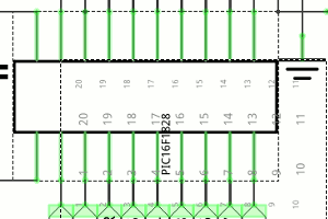
I was not aware that Fritzing did support net labels until after I had designed the circuit, but once I did I cleaned up the schematic as connection information was reflected back from the breadboard layout. On balance it made the circuit easier to understand, although a few connections such asCS1 & CS2 could have been laid out as wires without causing confusion. However I got caught out by a major bug in Fritzing that prevented further refinement: Sometimes the positioning of integrated circuits is shifted, as shown below, and once it happens the relative positions of the pin numbers gets irrecoverably screwed up.
This is a pity, because I have an overall positive view of Fritzing as a tool for the design and laying out of prototype circuits. While it is clearly deficient for design of PCBs and I abandoned it long ago in favour of KiCad, I have yet to find a decent alternative for breadboard circuit design. Fritzing seems to be under active development, but it has not had an official release for over two years, and I am not sure how much effort would be required to build it from a repository snapshot.
Board layout
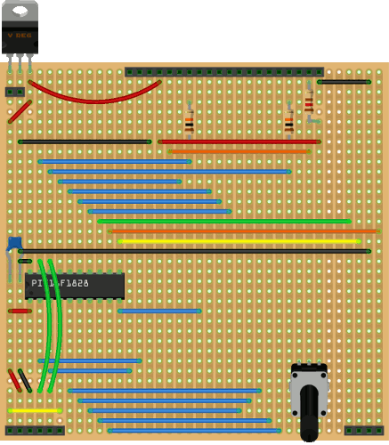
Originally I was going to use some 15-by-25 hole perf-board for the circuit, but I felt that this might be packing things in quite tightly due to the high ratio of connections to components, and needing to bend wires over to make contacts was something I did not feel like doing this time round. In the end I opted for 38-by-38 hole strip-board instead, which is also easier to lay out in advance. One consequence of this is being able to spread out the circuit, as shown below. As a result relatively few track cuts were needed — only 22 in total, and 10 of those are below the microcontroller itself. I decided it was best to have the LCD module itself resting on the board, rather than hanging off an edge. The layout below is very close to the layout on the physical circuit.
Backlight power supply
Although the data-sheet suggests the backlight should have a 3.5 volt power supply which nominally results in a recommended 64mA current draw, I felt this guidance to be of little practical value so ended up resorting to experimentation. Connecting the backlight to the 5-volt power rails directly drew around 70mA which I thought far too high, so I added in a series 120Ω resistor which resulted in a current draw of around 20mA and a backlight brightness which I considered bright enough. I suspect the backlight probably should be on a separate power supply to the control circuitry.LCD power supply
The module has some voltage inverting circuitry on-board, and as a bit-too-briefly mentioned in the data-sheet a potentiometer is supposed to be used as voltage divider to supply the LCD display, the latter of which requires a voltage within a fairly narrow band of 7.62-9.36 volts. This potentiometer in practice acts as a contrast control, and I found that it is that bit too sensitive to simply replace with a pair of fixed-value resistors, and have no idea of the viability of some sort of voltage regulating sub-circuit. Since the potentiometer is very much towards the positive side, I later added a 10kΩ fixed resistor the negative pin to help desensitise its effect on the contrast.Wire suitability
Wire is an issue I have previously discussed, and decent wire is one of those things that is surprisingly hard to obtain. The best wire I have come across is Maplin's solid-core pure-copper “bell wire” — solder seems to flow onto the pure copper much more readily than anything else I have come cross. I am not certain how thick it is, but based on theW020 code that is the same on all colours and comparing it with other wires I have, I suspect it is 20 AWG. However since Maplin went bust earlier in the year, my supply of this is finite and dwindling. The blue wire used to construct the circuit is some 26 AWG I originally sourced from Digi-Key (part number A422601L-50-ND) for use with perf-board where I needed a thinner wire that was easier to wrap around chip pins, but I found that often as not it would break when stripping it — perhaps not too surprising as the stripper states it is for 14-26 AWG. Wire more often than not only comes on reels of €20 plus, so ordering different types in to see how they perform is an expensive excercise.
Control Firmware
Originally this project was going to be used as a demonstration of two-register I2C transactions, but the implementation details related to these transactions was instead put into a seperate article. Therefore this article will only discuss more general details specific to control of the display. The complete firmware for thePIC16F1828 is available in Bitbucket, and may well be updated in the future. Although I included an external RS232 pin on the circuit board, it is at time of writing not used.
Display update protocol
An overview of pixel addressing is summerised in the diagram below. The two halves of the display are driven by seperate display chips, so they are de-facto indepedent of each other. Each half is divided into seven rows, each row consisting of 64 columns of 8 pixels each, with each 8-pixel column corresponding to a single byte. When a byte value is written, the column index auto-increments, wrapping around from 63 to zero.
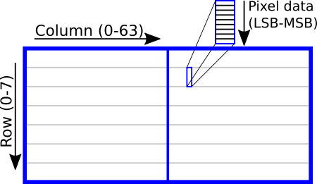
In I2C write transactions, the starting row and column are specified by the first and second register address bytes respectively, and the following data payload is pixel data. The firmware itself does not limit the length of the data, but due to wrap-around it does not make sense for this data to be longer thsn 64 bytes. If the two register bytes are both 0xff the display is cleared and filled using the pixel value that follows. Invalid row and column values within the I2C write result in a NACK.
Timings
The data-sheet implies that an entire enable line pulse cycle should last 1μs, but all the set-up and hold parameters relevant to writes are 140ns or less. However even at the maximum microcontroller clock speed of 16MHz the instruction execution time is 250ns, so a simple NOP or two is sufficient for timing purposes. At lower clock speeds one does not really need to care about timing delays, as coincidental overheads such as function calls are more than enough delay for the display.Reading from the display
At least at time of publication, I concluded that it was not worth implementing any read capability. The data-sheet for theNT7108C display controller chips mentions the need for “dummy reads”, which to me points towards reading from the display being a somewhat painful process to get working, and I see no real up-side in getting such functionality working. In scenarios where pixel data would need to be retrieved are ones where the controlling processor would most likely have the storage capacity for its own copy of the pixel data. I suspect the ability to retrieve pixel data from the display is intended for debugging rather than production use.
Data read-back is one thing, but I also think there is no point in implementing the reading of display status. Even though indications are that reading of display busy status does not have the turn-around time of other display transactions, the time it takes to switch the interface pins from output to input and back is quite likely longer than the processing time of any display commands. Typical of other LCD displays i have come across, closed-loop control does not seem worth the extra wire.
Display start line (broken scroll support)
According to what I assume is a later revisions of theNT7108 controller chip specifications, the display start line is used for display scrolling, although I doubt its practical use since the display's two side-by-side halves are driven by separate chips. I suspected that it was some sort of offset for the column, but from experimentation it either had no effect, or only caused a few of the columns to draw. Anecdotally it might be a partial feature that the LCD display doesn't include some extra wiring to properly enable, as the display data-sheet mentions things about duty cycles that are not relevant to those who are only concerned with the external interface.
Assembly snippets
It is not often that it make much difference writing firmware code in assembly rather than C, but in this case the speed-up from a little bit of hand-crafted inline assembly is noticeable. This is demonstrated in the screen clearing functionlcdClear() where the left side uses C code and the right side uses equivalent assembly code. Anecdotally the use of local variables — especially when passed as function parameters — seem particularly problematic, in part I suspect because PIC microcontrollers are far from memory-orientated. Although it is only the rewriting of the inner-most loop that makes the noticeable speed difference, having an entire block as assembly seems a lot cleaner than having lots of inline snippets. In fact the BSF (set bit) and BCF (clear bit) instructions are lot clearer then the equivalent C code, even though the compiler is smart enough to compile to the former assembly instructions. I suspect rewriting the core I2C routines in assembly is worthwhile, given the likelihood of using them in future projects with this chipset.