Bootstrapping ARM Cortex-M0
11 August 2018This article details how to use an Olimex JTAG debugger to program an NXP ARM Cortex-M0 microcontroller via a SWD (serial wire debugging) connection. It is the outcome of a first foray into ARM development, and covers the bootstrapping of a basic development circuit, using individual components in favour of an off-the-shelf demonstration board. Everything required, apart from a computer running Linux, should come to well below €100 all-in. Note that programming of firmware itself is beyond the scope of this article.
I opted for the Olimex ARM-USB-TINY-H, which although is not the cheapest JTAG debugger out there, is towards the lower end of the price spectrum. I chose it purely because it explicitly lists support for OpenOCD, which is reassuring because I started out with practically zero knowledge, and wanted a solution that I knew would work with Linux. The NXP LPC1112FD20/102,52 ARM Cortex-M0 is a low-end ARM microcontroller I chose because it is a relatively large SOIC-20 chip. It has 19KB of program memory and 4KB of RAM, which is small for an ARM but huge compared to the Microchip PIC controllers I have used in the past.
Hardware connections
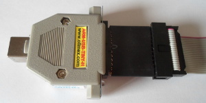
The OlimexARM-USB-TINY-H by itself does not support SWD (serial wire debugging), so to use SWD an ARM_JTAG_SWD adapter is required — looking at its schematic it has active components that multiplex bi-directional parallel signals rather than just remapping pins. It plugs in between the debugger and the ribbon cable, otherwise the input and output will be the wrong way round:
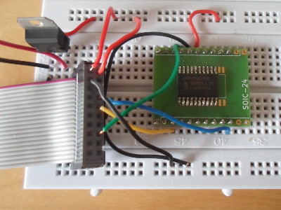
The connections between the other end of the ribbon cable and the ARM chip are wired manually using fly-leads, as shown in the picture at the top of the article, and the in mapping between the JTAG-standard and the chip pins are shown in the table below. Note that this table is laid out to be much like the receptacle top-down view, which is horizontally-flipped compared to the plug pins show in the picture above. All the JTAG/SWD pins are shown for reference, even though only a few are connected in this case.
| JTAG name | SOIC | Connector | SOIC | JTAG name | |
| Vcc sense | 15 | 1 | 2 | 15 | Vcc sense |
| TRST | - | 3 | 4 | 16 | Ground |
| TDI | - | 5 | 6 | - | Unused (ground) |
| TMS/SWDIO | 10 | 7 | 8 | - | |
| TCLK/SWCLK | 3 | 9 | 10 | - | |
| RTCK | - | 11 | 12 | - | |
| TDO/SWO | - | 13 | 14 | - | |
| Reset | 17 | 15 | 16 | - | |
| (5v supply) | - | 17 | 18 | - | |
| Unused | - | 19 | 20 | - |
Note that the table shows receptacle top-down view — if putting wires into the plug as shown in the picture ar the top of the article, the connections need t be mirrored horizontally. The NXP chip has internall pull-ups built-in, so external resistors are not required. Once eveything is connected up, try running OpenOCD.
Building OpenOCD
To avoid distribution-specific complications OpenOCD is built from source code, so first thing to do is clone the development repository:git clone https://git.code.sf.net/p/openocd/code openocd-src
For some reason cloning this repository takes quite a while. Once this is done build and install v0.10.0 of the code:
cd openocd-src git checkout v0.10.0 ./bootstrap ./configure --enable-fdti --prefix=/opt/openocd/v0.10.0 make make install
The code and associated configuration scripts will be installed into /opt/openocd/v0.10.0 (adjust the build commands to taste).
Connecting to the ARM Cortex
Once OpenOCD and been built and installed, use the following command to connect the OlimexARM-USB-TINY-H and ARM_JTAG_SWD to the NXP LPC1112 ARM chip. It is a little bit more verbose than it needs to be, but it can be run from any location:
BASE=/opt/openocd/v0.10.0; ${BASE}/bin/openocd \ -f ${BASE}/share/openocd/scripts/interface/ftdi/olimex-arm-usb-tiny-h.cfg \ -f ${BASE}/share/openocd/scripts/interface/ftdi/olimex-arm-jtag-swd.cfg \ -f ${BASE}/share/openocd/scripts/target/lpc11xx.cfg
If successful, you should see the following output:
Info : FTDI SWD mode enabled adapter speed: 10 kHz adapter_nsrst_delay: 200 cortex_m reset_config sysresetreq Info : clock speed 10 kHz Info : SWD DPIDR 0x0bb11477 Info : lpc11xx.cpu: hardware has 4 breakpoints, 2 watchpoints
You are now ready to flash some firmware to the chip, although this is beyond the scope of this article. This will be covered in a future tech section article (now available) as the development and deployment of ATM firmware is software development exercise.
Things not working
This section deals with some scenarios of failure — if things did not work after following the previous section, you might instead get output as shown in one of the sub-sections below. If this is the case, see the troubleshooting notes written within the relevant sub-section.Device not found
Info : FTDI SWD mode enabled adapter speed: 10 kHz adapter_nsrst_delay: 200 cortex_m reset_config sysresetreq Error: no device found Error: unable to open ftdi device with vid 15ba, pid 002a, description 'Olimex OpenOCD JTAG ARM-USB-TINY-H', serial '*' at bus location '*'
The FDTI drivers are included as standard in recent Linux kernels, so this is mostly likely caused by the device being disconnected, or a fault with the cable/hub it is connected via.
Access error
Info : FTDI SWD mode enabled adapter speed: 10 kHz adapter_nsrst_delay: 200 cortex_m reset_config sysresetreq Error: libusb_open() failed with LIBUSB_ERROR_ACCESS Error: no device found Error: unable to open ftdi device with vid 15ba, pid 002a, description 'Olimex OpenOCD JTAG ARM-USB-TINY-H' and serial '*'
This is a permissions issue. You can either run the commands as root, or you can add a file with the following one-line UDev rule into /etc/udev/rules.d/ — since no-one else uses my system, this simply makes the device available to all users unconditionally:
SUBSYSTEM=="usb", ACTION=="add", ATTR{idProduct}=="002a", ATTR{idVendor}=="15ba", MODE="666"
To reload UDev rules without rebooting the system, at least on Slackware Linux, the following commands can be used:
udevadm control --reload-rules udevadm trigger
OpenOCD exits after some input
Info : FTDI SWD mode enabled adapter speed: 10 kHz adapter_nsrst_delay: 200 cortex_m reset_config sysresetreq Info : clock speed 10 kHz in procedure 'init' in procedure 'ocd_bouncer'
This is caused when the ARM chip itself is either disconnected or is not powered up. OpenOCD is not very helpful in situations where not everything is connected.
Parts list
This list is intended as a rough-guide as to what components are required to recreate the circuit in this article, and includes some extras that may be useful with future projects rather than being strictly required. Of particular note is that I used a custom-made SOIC-to-DIP adapter, rather than the one listed below, as most off-the-shelf adapters are overpriced. Prices are correct at time article was written — Farnell cut some of the prices by 10-15% in the time since I ordered them, so prices are just a guide as to where money will be spent.
| Item description | Manufacturer Code | Farnell code | Unit cost |
| Olimex ARM debugger | ARM-USB-TINY-H |
2144330 | €50 |
| Olimex SWD adapter | ARM_JTAG_SWD |
2144329 | €6.18 |
| 20-pin to 10-pin adapter | ARM-JTAG-20-10 |
2144328 | €6.18 |
| NXP Cortex-M0 (SOIC-20) | LPC1112FD20/102 |
2470837 | €2.07 |
| SOIC24 to DIP adapter | RE936-09 |
2474727 | €2.34 |
| 3.3 volt power regulator | LD1117V33C |
1703357 | €0.37 |
Overall I feel that I would be hard-pressed to get a hardware ARM development platform & kit together for much less than the sum of the above prices. Most of the cost is the debugger, and I think this is the one thing that is worth investing a bit on rather than simply going for the cheapest one on E-Bay. Flip side of the coin I think the ones that cost several hundred Euros are not worth the mark-up, and I suspect many of them are only compatible with propriety software that may well not run on Linux.