PIC16F630 de-bouncer
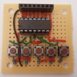
27 April 2018This is a small circuit that provides six active-high buttons that are de-bounced. I built it as I was testing out an integrated circuit that seemed particularly sensitive to electrical contact bouncing, and for some time I had been considering building a board that provided an array of buttons complete with pull-downs to avoid floating voltages. It is based around a
PIC16F630, using a method of de-bouncing that was used in a past circuit.
From the outset I decided that the input pins should all be on one side of the chip, and for each input pin the corresponding de-bounced output should be directly opposite on the other side of the chip. This simplifies the chip from a hardware component perspective, but does cause complications because the input and output pins are split between the two ports.
Internal vs. external pulling resistors
ThePIC16F630 microcontroller has programmatically-enabled internal pull-up resistors, which I have taken advantage of in previous circuits, but since they are only available on PORTA and not PORTC I disabled them and used external pull-down resistors. Adding pull-down resistors to all the pins removes a factor — namely whether an input already has an internal pulling resistor — that needs to be kept track of, and in any case my preference is for active-high rather than active-low.
De-bouncing firmware
The entire source code for the firmware is on Bitbucket. Using Timer0 each input pin is sampled every 0.128ms, and if the last samples are the same — either high or low — the corresponding pin is updated to high or low as appropriate. The input and output pins are not in a convenient order, so the code is a somewhat bulky if-then-else chain rather than a concise calculation, and I suspect that in this case looping over arrays rather than manually unrolling the loop actually increases the size of the compiled code. I possibly could have used lookup tables, but I think doing so involves EEPROM reads, the efficiency of which I have not looked into. In any case the firmware is “fast enough”.
One issue that came up with the firmware was the sampling delay. The PIC16F630 chip has a 4MHz clock, so FOSC/4 should be 1MHz, and prescaling this 1:128 should result in a period of 0.128ms — with 8 samples being taken this means a button press needs to last about 1ms to be registered as valid. However I noticed that “short” button presses were getting suppressed, which was solved by reducing the Timer0 prescale to 1:32. From past experience the only cases where the expected delay of PIC timers, based on interpretation of the data-sheets, has matched wall time has been with projects such as the 8-segment LCD timer where an external timing crystal has been used.