PIC16F88 LED alarm clock
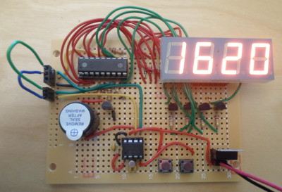
01 April 2018This circuit is a recreation of the PIC16F88 Timer, rebuilding the
PIC16F88-controlled part of the timer with a single Kingbright CA56-12SEKWA 4-digit LED chip (Farnell 2478712) rather than the four 1-digit displays used previously, and with the addition of a Multicomp MCABI-020-RC (Farnell 2361099) as an audible alarm. Originally I intended not to create a fully working timer, but the PIC12F1822 based timing & input subsystem was not much additional effort to add in, particularly as there was ample space left for it.
It was luck that I happened to come across the 4-digit LED modules, and I ordered in some samples because I remember that wiring up the four single-digit LED chips in the previous displays was a significant portion of the effort. I had intended to use an LCD display rather than LED modules for the next iteration of timer boards, but the daughter-board I had ordered for the LCD timer & display is not expected to arrive for some time.
Circuit design
The previous single-digit LED chips were common-cathode (i.e. the common pin is ground), but the new four-digit ones are common-anode, so the current flow was reversed. I had thought about omitting the transistors entirely, but doing so would have meant a high reverse-voltage when an LED was switched off, which I suspect would damage it — instead I replaced current-sinking NPN transistord with current-sourcing PNP transistors, and thePIC16F88 would act as a current sink rather than a current source. As before I chose the wiring to notionally avoid the LED power wires crossing, but made an exception for the dot pin (the white wire) as PORTA on the PIC16F88 only has 7 output-capable pins, and I decided tht the dot should be the segment that is on PORTB. The circuit as laid out in Fritzing is shown below.
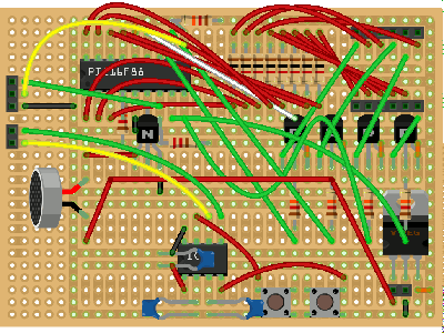
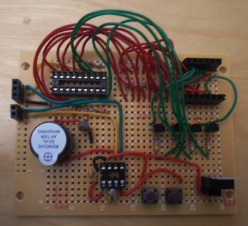
I have used a microphone as a place-holder for the sounder and the timer crystal is missing, but otherwise the above image is an accurate representation of the actual circuit which is shown below — Fritzing is a good piece of software, but it lets itself down so much in having to resort to place-holders. The much smaller footprint required for the single LED chip has meant the circuit is nowhere near as tightly packed as the previous timer circuits, and at a push could have had all the LED-related components in the upper half of the board, by squeezing together the PNP transistors and their base-current resistors. The two microcontrollers having separate receptacles for the I2C lines rather than being internally connected is an artefact of the original intention for not including the timing-keeping & input sub-circuit.
Sounder wiring
I tried out several sounders, but most of them were either physically too big or had an awful pitch, and in the end I settled for the MulticompMCABI-020-RC (Farnell 2361099). One issue is that this sounder is rated 12 volts, so a 5-volt circuit would be insufficient to power it — instead the sounder is connected directly to the unregulated external power supply, and it is switched on & off using a sinking NPN transistor connected between the ground terminal and the circuit ground power rail. The proof-of-concept circuit for this is shown below.

Component ratings
The previous LED display circuit used 800Ω current-liming resistors, but for stock reasons I opted for 1kΩ ones for this circuit, and the LED chip still seemed bright enough. The new LED chip had a stated typical voltage drop of 2 volts in its data-sheet, which in 5-volt circuit means 3 volts would be across the protective resistor, and with this resistor being 1kΩ would allow a current draw of 3mA — this calculation proved accurate as the measured current was 3.07mA. For the transistor base resistors I used my usual 12kΩ and assumed a voltage drop of 4 volts, although in reality the voltage drop was 4.2 volts, the latter implying a base current of 0.35mA.
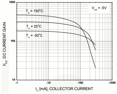
The BC556B PNP transistors have a head-line gain of 200, but looking at the graphs in the data-sheet — the DC Gain graph is reproduced above — for the ON-Semi units I use (Farnell 2453802), the actual gain for the expected operating parameters is a lot closer to 300. Such a gain would easily pass the 24mA of all segments being lit, and at a push I probably could use some of my 78kΩ resistors.
Firmware changes
Because thePIC16F88 is sinking current rather than sourcing it, the firmware has logical-low as on rather than logical-high as was the case previously. The wiring of the segments is also different, so all the display-related bit-patterns needed to be changed, but this did not change the structure of the firmware code. This time round I decided to use #define's and build up the bit patterns, rather than just having an array of the distilled-down hexadecimal values:
#define SEG_MASK 0b11011111 #define SEG_A 0x10 #define SEG_B 0x04 #define SEG_C 0x01 #define SEG_D 0x80 #define SEG_E 0x40 #define SEG_F 0x08 #define SEG_G 0x02 #define SEG_DOT 0x80 unsigned char segs[11] = { SEG_A|SEG_B|SEG_C|SEG_D|SEG_E|SEG_F, SEG_B|SEG_C, SEG_A|SEG_B|SEG_G|SEG_E|SEG_D, SEG_A|SEG_B|SEG_G|SEG_C|SEG_D, SEG_F|SEG_G|SEG_B|SEG_C, SEG_A|SEG_F|SEG_G|SEG_C|SEG_D, SEG_F|SEG_G|SEG_E|SEG_D|SEG_C|SEG_A, SEG_A|SEG_B|SEG_C, SEG_A|SEG_B|SEG_C|SEG_D|SEG_E|SEG_F|SEG_G, SEG_A|SEG_B|SEG_F|SEG_G|SEG_C, SEG_A|SEG_F|SEG_G|SEG_E|SEG_F };
In the I2C mini-protocol the lower nibble of the third byte controls the dots on the LED display, which I extended with the upper nibble controlling whether the sounder should be activated. Since I preferred an intermittent sound rather than a continuous one, I put in a toggling parameter that is driven using a periodic Timer2. The output needs to be frequency-divided because this timer is limited to a maximum period of 64ms.
if( TMR2IF ) { TMR2IF = 0; iBeepCnt++; if(iBeepCnt == 10) { /* Frequency-divide Timer2 output */ iBeepCnt= 0; iBeepOn ^= 0xff; } } if( iBeepOn && (iDot & 0xf0)) { /* Force all dots on and power up sounder */ PORTB &= ~SEG_DOT; PORTB |= 0b1; } else { /* Power down sounder */ PORTB &= ~0b1; }
Unlike Timer0 and Timer2 which use 8 bits, Timer1 uses 16 bits to specify the time delay, but the latter is already in use for the LED refresh cycle so was not available for controlling the sounder bursts. I also felt it was better to control the bursts from the LED-control microprocessor rather than off-loading it onto the timing & input control chip, in part because I originally did not intend to include the latter in the circuit. I also considered using the available 4 bits in the I2C protocol to specify different burst lengths, but in the end kept things simple.
Remarks
My longer-term plan was to use an LCD display rather than LEDs for the next iteration of my timer, but needing a 12-volt power supply (9-volt square batteries are pushing it) for the sounder negates the low-power benefits of using an LCD display, and using a single 4-digit LED chip simplifies the design significantly. This circuit was not intended to be a complete timer, instead of just being a test of said 4-digit LED chips, but I had the components in stock and time to kill. In the longer-term I am considering putting the firmware source code into Githib or Bitbucket.
The miswired pull-up resistor in hindsight resulted in this board taking twice as long to complete as it ought to have — originally I hot-patched this board to my previous LED display for testing purposes, but that did not work and at the time I assumed it was due to the two boards having separate power supplies. The hot-patching worked in the other direction so I narrowed it down to a problem with the PIC16F88 on this new board, and it was only after a while in headless-chicken mode I noticed that the resistor might be in the wrong place.