74HC238 expander
30 March 2018The
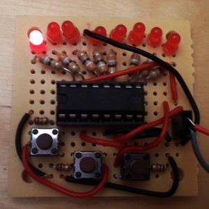
74HC238 is a parallel output expander that converts 3-bit binary into an 8-bit output, where the input decides which one of the outputs is set high. Multiple manufacturers make their own variants of the chip, but for this article I used the Texas Instruments' variant because of the availability of a DIP-16 version (CD74HC238E, Farnell 2260025). I also used the making of a test board as an opportunity to test out some small perfboard prototyping boards.
Had I known about about this particular chip at the time, I have no doubt that many of my earlier projects would have been designed very differently, because there have been cases where I would have wanted to use 3 bits of binary to decide which of eight power lines to activate. For instance when building my LED matrix display I could have used a single 8-bit PCF8574 I/O expander to power a single LED module independently, with 5 bits sinking the column currents and the remaining 3 bits indicating which row should be powered.
Wiring
The74HC238 is almost straightforward to wire up, but for reasons which I think just complicate use of the chip, there are three enable lines — of which two are negated so things are a bit more complex than just tying them all to the same power rail. If there were just a single enable line I would have been happy to drop this chip straight into a PCB design with only reference to the data-sheet, but having three enable lines to me was an over-design that meant I wanted to experiment with the chip in isolation first. The wiring I used for the TI CD74HC238E is shown below.
| Wiring | Power | Output | ||||||
| Purpose | Vcc | Bit 7 | Bit 6 | Bit 5 | Bit 6 | Bit 3 | Bit 2 | Bit 1 |
| Pin | 16 | 15 | 14 | 13 | 12 | 11 | 10 | 9 |
| Pin | 1 | 2 | 3 | 4 | 5 | 6 | 7 | 8 |
| Purpose | A0 | A1 | A2 | Enable | Bit 0 | Gnd | ||
| Wiring | Input | Tie to Ground | Tie to Vcc | Output | Power | |||
There was not have room to include a voltage regulator on the board, and in any case I think including one would have been excessive for a simple test board such as this one. In any case even though it was out of spec it still operated when connected to a 12-volt power source, but for a low-power circuit such as this one only running for short periods there would not be any damage.
Soldering perfboard
I ordered in some small perfboard prototyping boards (Farnell 2768276) just to see what they were like, and using it to make a test board for the expander felt like the perfectly-sized mini-project. Normally I would have just used solderless breadboard, but setting up so many LEDs and resistors is such a pain I decided I wanted something more permanent, and in any case I had plenty of LED & resisitors in stock. With perfboard none of the holes are connected, and from what I had read the technique is to bend over wires to connect adjacent holes, which is what I did as shown below.
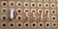
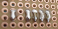
I have heard mixed views whether just laying out lines of solder is right or wrong, but my general impression is that you need the wires there so that the solder flows into the right places. The results look ugly, but particularly in cases like this where the board is built ad-hoc rather than to a design, it felt a lot more flexible than my usual prototyping — I doubt that I could have squeezed all this stuff into the same area of either stripboard, or even my usual IC prototyping board. The advantage of creating tracks rather than removing them is no having the limitation of direction, which is a big compromise I have had when using stripboard.
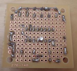
The one big irritation is that soldering in of components are no longer independent of each other, so at times components have to be left in a less-than-secure position, which was most notable with the IC socket. Normally IC sockets would be the first things I solder in place, but trying to add in a wire to an existing solder joint is a recipe for poor electrical conductivity. I would not recommend perfboard to someone who is starting out, and in the past I have deliberately avoided this type of prototyping board, but I now feel that it is quite good for projects that are not IC-dominated.