LED display (part 2)
31 July 2017The notional aim of this project was to create a small LED display capable of showing messages, although in practice this was merely a context for practice at building circuits. For better or worse I decided that I would split the circuit over multiple boards, and the first article covers the crash-course in soldering that making the LED board turned out to be. In this second part I cover the creation of the latch board, which contains the D-type latches that will drive each row of LEDs.
Prefabrication
Fritzing had a menu item labelled order PCB board and I decided what the heck and to give it a try. The board was quoted at €10 each which in itself I felt was an OK price for something that was a complete punt in the dark, but annoyingly orders have to be multiples of three which made this a somewhat expensive project. In order to keep board size down I explicitly included external wires, but in hindsight this was perhaps a little self-defeating. Anyway below is one of the pre-made boards:
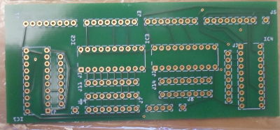
The auto-routing of the tracks resulted in a bit of a mess, but this was a first-attempt and I did not know any better. Although there was no cost advantage in it, I probably could have got away with a single-layer board, as pretty much all the cross-overs were done with external wires. In hindsight it is surprising how much board real-estate is taken up by tracks rather than component holes. Since getting these boards and finishing this article I have made much more effective use of prefabricated boards, but that is a story for another time.
The complete board
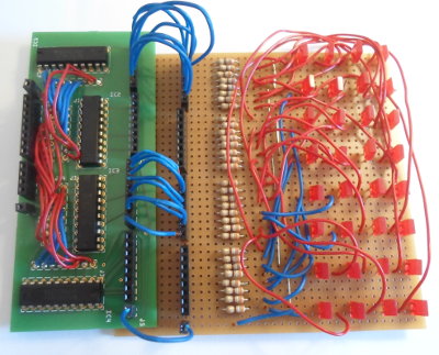
Wiring up the board and soldering in the latch chips was actually quite easy, but some of the connector placement could have been a lot better. Probably should have tried securing them in place with blu-tack, but I did not have any to hand — this is the sort of trick that comes from experience. The single-wire receptacles were particularly troublesome, and given their high cost compared to the 8-lane receptacles, probably should have excluded them from the design. Below shows the LED & latch board attached to each other, though for clarity not all the inter-board wires are present.
In hindsight I think commissioning this board was not one of my better ideas, but it is all experience and experience is what really matters. The big lesson from making this board is that fanning out wires is actually quite difficult, and it would explain why these days there seems to be a preference for serial interfaces over parallel ones. Because the circuit is spread over multiple boards one thing I looked into was various options for wiring the boards together, because stripping and attaching around 50 fly-leads is actually a complete pain to do. However the plugs and receptacles for ribbon cable turned out to be surprisingly expensive, and in any case bought the problem of routing signals to the sockets themselves.
Costing
Costing is somewhat distorted because electronics suppliers such as Farnell quote different prices depending on order size — the 390 Ohm resistors I bought in bulk (strip of 500) so they worked out at 2.5¢ each, and I got a sizeable order of the cheapest red LEDs that worked out at 7.3¢ each. In some cases ordering as little as 5 or 10 units results in the unit price halving compared to ordering a single unit. The stripboard worked out at €2.66, but the price of some of the other passive components seemed relatively high for what they were. The 8-way connectors came to 49¢, but the single-way connectors came to an extortionate €1.46 each. All-in below is a fairly representative list of component costs for the project:| Item | Code | Quantity | Total cost |
| Stripboard | 2503759 | 1 | €2.66 |
| LED | 2314275 | 32 | €2.32 |
| Resistor | 2329671 | 32 | €0.79 |
| 8-way header socket | 1593463 | 4 | €1.97 |
| 1-way header socket | 2308467 | 1 | €1.46 |
| 8-bit D-type latch | 9592091 | 4 | €2.43 |
| Custom PCB | n/a | 1 | €10.00 |
| AWG38 Wire (red) | n/a | 1 | €9.55 |
| AWG22 Wire (blue) | n/a | 1 | €4.15 |
| Solder | n/a | 1 | €4.45 |
The last three items are hard to apportion a cost, but in the case of the solder I am pretty certain that the whole LED display project — aborted attempts included — got through the entire tube of solder. What I found is that a lot of the bigger costs were bulk items that have huge mark-ups when bought in small quantities, and the biggest costs (not shown here) was capital expenditure of various tools you suddenly realise you need. For instance when using stripboard there is the need for a tool to drill out tracks you don't want signals going down. I have the suspicion that I easily spent €600-800 in total, but that includes things such as a decent soldering station (at time of writing yet to arrive) that in itself came to €150.
Conclusion
The first part was a complete crash-course in soldering, whereas in this part soldering actually felt a very small part of the whole exercise. This time round the decision to use a custom PCB meant the whole experience was very different, most notably was more attention being paid to higher-level issues such as costing and up-front component selection. The big enabler for this part was much better use of Fritzing, which has its fair share of irritations, but laying a circuit out in Fritzing in practice is actually a good starting point. First time round I used it to work out where track drill holes needed to go, but this time round I took advantage of how it links together the breadboard, schematic, and PCB layout views. This was good at catching mistakes before they caused problems, and was essential with something as water-fall as ordering in PCB designs.Custom PCB layout is actually quite enjoyable — there were irritations but it was much better experience than the headache that is working with stripboard. There are several reasons why it turned out this way, which are elaborated below, although I suspect that this being a second mini-project rather than the first played a part.
- Wiring doesn't dominate
- With stripboards where components get placed is influenced by where wiring will go, and quite often components that connect to each other are not actually neighbours. With PCBs component placement comes first, and to a large extent all that is needed is for enough room to be left for signal tracks.
- Greater flexibility
- With stripboard orientation & placement of components is limited by track direction, particularly with integrated curcuits, but with PCBs there is so much more freedom in where components can go.
- Fritzing (software design) support
- As is the case with physical breadboard (both solderless and soldering) the placement of wires within Fritzing is messy, but with the PCB view this is not the case. It is complex in its own way, but laying out PCB signal tracks on the whole is a nicer experience than how it handles fly-leads.
- Custom PCB is cost-effective
- Stripboard is actually quite expensive, and apart from a few 10cm-by-10cm offerings the price range is pretty much €7-20. With this in mind €10 for a custom-printed PCB actually seems quite good, and I have other such orders in the pipe-line which I will write about at a later date.
- Clearer indication where things are to go
- When it came to soldering everything into place once I had got my PCB it all seemed to go like a breeze. A constant headache with the first part was keeping track of where things are meant to go, but with a PCB I was concentrating on the task of securing things in place.
- Compactness
- A custom PCB is a lot smaller than what an equivalent design would be on stripboard. A lot of my subsequent PCB orders, which I will write about at a later date, are daughterboards that I designed purely because of the ability to do things in a much smaller space.